Différences entre versions de « ENG-CANSAT-V2-PINOUT »
Sauter à la navigation
Sauter à la recherche
| Ligne 1 : | Ligne 1 : | ||
| + | {{ENG-CANSAT-PICO-NAV}} | ||
| + | |||
== Power Section == | == Power Section == | ||
This collect the information about the power circuitery for the Cansat V2 and the project. | This collect the information about the power circuitery for the Cansat V2 and the project. | ||
| Ligne 20 : | Ligne 22 : | ||
Remarks: | Remarks: | ||
# The 3V3 of MCU bpard is not shared with the | # The 3V3 of MCU bpard is not shared with the | ||
| + | |||
| + | {{ENG-CANSAT-PICO-TRAILER}} | ||
Version du 25 juillet 2025 à 00:19
Power Section
This collect the information about the power circuitery for the Cansat V2 and the project.
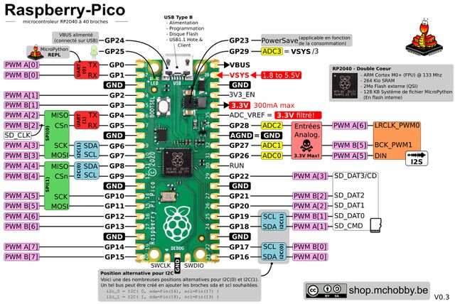
The MCU Board (the Pico) is responsible from its own power regulation.
It can be powered from:
- USB connector: so with 5V. That voltage will be made available on the USB pin.
- VSYS pin : with a voltage from 3 to max 5.5V. A battery can feed that Pin
The MCU board (Pico) can be easily shutdown by placing its 3V3_EN pin to the ground.
Doing so, the Pico 3.3V DC/DC regulator will deactivates, shutting down the MCU and spare the battery power.
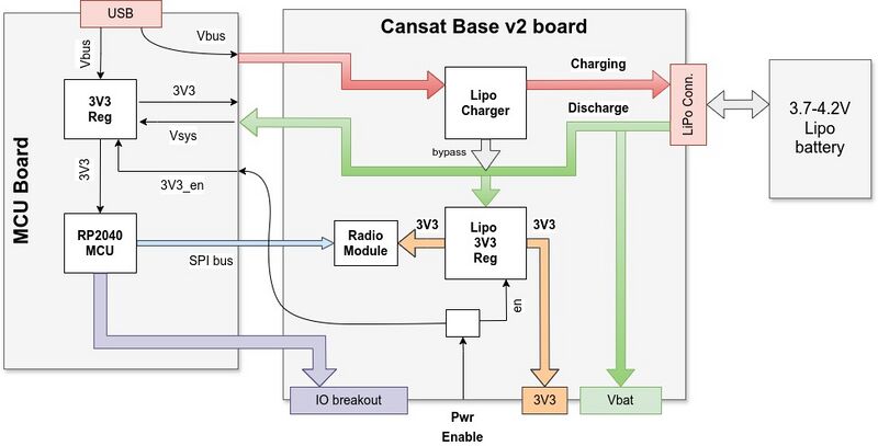
The following diagram show the power distribution with relation.
Remarks:
- The 3V3 of MCU bpard is not shared with the
Written by Meurisse D. for MCHobby

