Différences entre versions de « ENG-CANSAT-V2-ASSEMBLY »
(Page créée avec « {{ENG-CANSAT-PICO-NAV}} == Abstract == The {{pl|2271|original version of the CANSAT kit}} required many soldering operation. It's intimidating for newcomers with little e… ») |
|||
| (16 versions intermédiaires par le même utilisateur non affichées) | |||
| Ligne 4 : | Ligne 4 : | ||
The {{pl|2271|original version of the CANSAT kit}} required many soldering operation. It's intimidating for newcomers with little experience with a soldering iron. | The {{pl|2271|original version of the CANSAT kit}} required many soldering operation. It's intimidating for newcomers with little experience with a soldering iron. | ||
| − | With the {{pl||CANSAT V2 kit}}, things have been made | + | With the {{pl||CANSAT V2 kit}}, things have been made easier than ever, no solder required! |
== Assembling the Cansat == | == Assembling the Cansat == | ||
| − | + | Let's prepare the main CANSAT board. | |
| − | + | [[fichier:ENG-CANSAT-V2-CONTENT-10.jpg|640px]] | |
| − | |||
| − | [[fichier:ENG-CANSAT- | ||
| − | |||
| − | |||
{{asm-begin}} | {{asm-begin}} | ||
| − | {{asm-row|img=ENG-CANSAT- | + | {{asm-row|img=ENG-CANSAT-V2-ASSEMBLY-10.jpg}} |
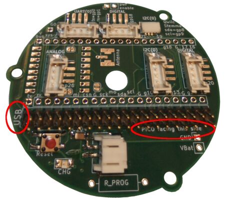
| − | {{asm-text}} | + | {{asm-text}}Take the base board and orient the board to see the '''USB''' label on the left and the "Pico/MCU facing this side" in front of you. |
| − | |||
| − | |||
| − | |||
| − | |||
| − | |||
| − | {{ | + | {{asm-row|img=ENG-CANSAT-V2-ASSEMBLY-11.jpg}} |
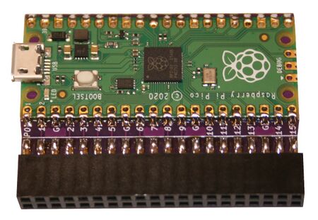
| + | {{asm-text}} Grab the CPU board with the microcontroler facing front. | ||
| − | + | {{asm-row|img=ENG-CANSAT-V2-ASSEMBLY-12.jpg}} | |
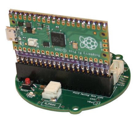
| + | {{asm-text}} Now, insert the MCU board onto the 2x20 pin connector. | ||
| − | {{asm-row|img=ENG-CANSAT- | + | {{asm-row|img=ENG-CANSAT-V2-CONTENT-10.jpg}} |
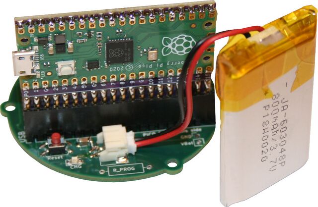
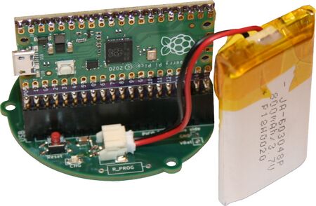
| − | {{asm-text}} | + | {{asm-text}} Even when not required yet, user can pick the Lipo battery then plug it into the 2 poles JST connector (facing the microcontroler). |
| − | {{ | + | {{ambox | text = As soon as the battery is connected it will start to discharge in the board. The discharge can be compensated: |
| − | + | * either by plug in power on the USB connector. | |
| + | * either by shorting the pads of "PWR Enable" connector (MCU sill also shutdown).}} | ||
| − | + | {{asm-row|img=ENG-CANSAT-V2-ASSEMBLY-14.jpg}} | |
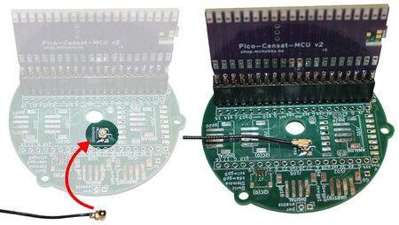
| + | {{asm-text}} '''Antenna must be connected before any communication attempt!''' | ||
| − | + | To do so, connect the µFl coaxial wire on the board then connect the demo antenna to the other side. | |
| − | + | {{tmbox | type = speedy | text = Long range communication will requires dedicated antenna tuned for their final usage. HAM Club is the right place to get started.}} | |
| − | |||
| − | |||
{{asm-end}} | {{asm-end}} | ||
| − | == | + | == Assembling the base station == |
| − | |||
| − | |||
| − | |||
| − | |||
| − | |||
| − | |||
| − | |||
| − | The | + | The base station also gets improvements. No more soldering this side too. |
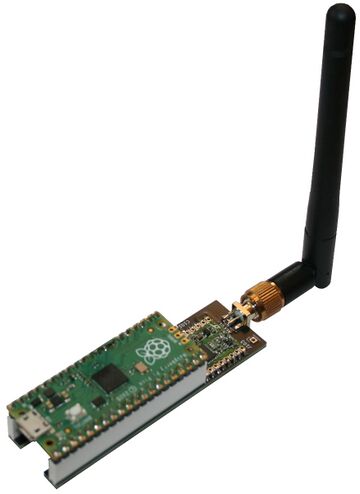
| − | + | Within the CANSAT-KIT the Rapsberry-Pico is ready to use and can be plugged onto an PICO Radio board. | |
| − | [[ | + | [[Fichier:ENG-CANSAT-V2-ASSEMBLY-20.jpg|360px]] |
| − | + | Connects the demonstration 433 MHz Antenna and you are ready to test. | |
{{asm-begin}} | {{asm-begin}} | ||
| − | {{asm-row|img=ENG-CANSAT- | + | {{asm-row|img=ENG-CANSAT-V2-ASSEMBLY-21.jpg}} |
| − | {{asm-text}} Pico | + | {{asm-text}} Grab the RFM69-Boot expansion for Pico. |
| − | |||
| − | |||
| − | + | When included within the CANSAT-KIT: | |
| − | + | * the expansion board have the femalle header pre-soldered. | |
| + | * an extra antenna conector is also included and pre-soldered. | ||
| − | {{ | + | {{asm-row|img=ENG-CANSAT-V2-ASSEMBLY-22.jpg}} |
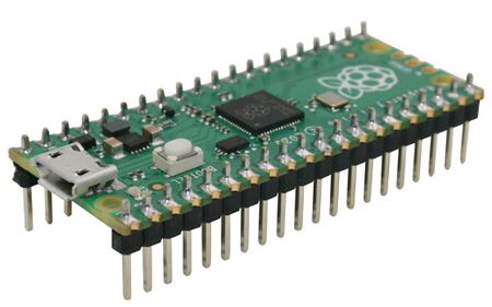
| + | {{asm-text}} Grab the Pico microcontroler. | ||
| − | + | When included within the CANSAT-KIT, the header is pre-soldered on it. | |
| − | |||
| − | {{asm-row|img=ENG-CANSAT- | + | {{asm-row|img=ENG-CANSAT-V2-ASSEMBLY-23.jpg}} |
| − | {{asm-text}} | + | {{asm-text}} Plug them together. |
| − | + | Notice that USB connector goes over the opening of the Pico-RFM69-BOOT. | |
| − | + | It is now time to connect the 433 Mhz test antenna included in the Kit. | |
| − | {{ | + | {{tmbox | type = speedy | text = Long range communication will requires dedicated antenna tuned for their final usage.<br />HAM Club is the right place to get started.}} |
| − | |||
| − | |||
| − | |||
| − | |||
| − | |||
| − | |||
{{asm-end}} | {{asm-end}} | ||
{{ENG-CANSAT-PICO-TRAILER}} | {{ENG-CANSAT-PICO-TRAILER}} | ||
Version actuelle datée du 31 juillet 2025 à 14:01
Abstract
The original version of the CANSAT kit required many soldering operation. It's intimidating for newcomers with little experience with a soldering iron.
With the CANSAT V2 kit, things have been made easier than ever, no solder required!
Assembling the Cansat
Let's prepare the main CANSAT board.
Assembling the base station
The base station also gets improvements. No more soldering this side too.
Within the CANSAT-KIT the Rapsberry-Pico is ready to use and can be plugged onto an PICO Radio board.
Connects the demonstration 433 MHz Antenna and you are ready to test.

|
Grab the RFM69-Boot expansion for Pico.
When included within the CANSAT-KIT:
| ||
|
Grab the Pico microcontroler.
When included within the CANSAT-KIT, the header is pre-soldered on it. | ||

|
Plug them together.
Notice that USB connector goes over the opening of the Pico-RFM69-BOOT. It is now time to connect the 433 Mhz test antenna included in the Kit.
|
Written by Meurisse D. for MCHobby
