Différences entre versions de « ENG-CANSAT-MISSION1-CAPTURE »
Sauter à la navigation
Sauter à la recherche
(→Wiring) |
|||
| Ligne 7 : | Ligne 7 : | ||
and transmissing the information via the RFM69HCW radio module. | and transmissing the information via the RFM69HCW radio module. | ||
| − | + | {{ambox|text=Before starting this point, we recommand to follow all the sensors testing steps (BMP280 sensor, TMP36 Sensor, RFM69HCW radio and RFM69HCW Testing). | |
| + | |||
| + | It contains all the details about the wiring, install needed libraries and conduct basic testing.}} | ||
| + | |||
== Wiring == | == Wiring == | ||
=== Wire the barometric sensor === | === Wire the barometric sensor === | ||
Version du 28 octobre 2018 à 14:39
Introduction
The following Wiring is used to capture
- Air temperature
- Air pressure
and transmissing the information via the RFM69HCW radio module.
| Before starting this point, we recommand to follow all the sensors testing steps (BMP280 sensor, TMP36 Sensor, RFM69HCW radio and RFM69HCW Testing). It contains all the details about the wiring, install needed libraries and conduct basic testing. |
Wiring
Wire the barometric sensor
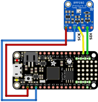
The BMP280 is wired on the I2C bus of the Feather.
Wire the temperature sensor
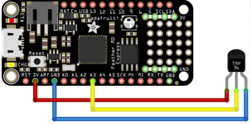
Connect the TMP36 sensor as follows:
- The pin 1 (on the left) to a power source (3.3V),
- The pin 3 (the the right droite) to the ground/GND.
- The pin 2 (middle one) to the A3 analogue input.
Wire the radio module
Finally wire the RFM69HCW radio as follows:
Written by Meurisse D. from MC Hobby - License: CC-SA-BY.

