Différences entre versions de « ENG-CANSAT-PICO-MISSION1-RECEIVE »
| Ligne 92 : | Ligne 92 : | ||
Before using {{fname|cat}}, we do need to identifies the computer device attached to the USB-Serial connection. | Before using {{fname|cat}}, we do need to identifies the computer device attached to the USB-Serial connection. | ||
| − | The {{fname|dmesg}} command line tools inspecting kernel | + | The {{fname|dmesg}} command line tools inspecting kernel messages can greatly helps to identify the device name. |
| + | |||
| + | In the following capture, it is possible to identify the newly plugged USB device as '''ttyACM1''' (so /dev/ttyACM1) | ||
[[Fichier:ENG-CANSAT-PICO-MISSION1-RECEIVE-20.png]] | [[Fichier:ENG-CANSAT-PICO-MISSION1-RECEIVE-20.png]] | ||
| − | + | ||
=== Catching the data === | === Catching the data === | ||
{{ENG-CANSAT-PICO-TRAILER}} | {{ENG-CANSAT-PICO-TRAILER}} | ||
Version du 6 mars 2022 à 22:16
Introduction
The following wiring will prepare the Receiver "Base Station" for the mission 1. From the "RFM69HCW Testing" section, we will use a Raspberry-Pico wired to a RFM69HCW module in order to capture the Radio Messages and redirect them the USB-Serial connection.
As such, we will be able to receive (and even store) the data sent by the CanSat emitter.
Wiring
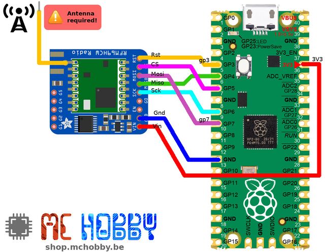
Here how to wire the RFM69 module to the Raspberry-Pi Pico.
Here is the description of wiring between the Pico and the RFM69 module.
| RFM69HCW | PICO |
|---|---|
| RST |
GP3 |
| CS | GP5 (Slave Select) |
| MOSI | GP7 (Miso) |
| MISO | GP4 (Mosi) |
| SCK | GP6 (Clock) |
| GND | GND |
| VIN | 3V3 |
Download the code
The code is available for download on the GitHub associated to this wiki.
About testing
Once the script basestation.py renamed as main.py and uploaded to the board, just restart the board to make it running.
| It also possible to start the script from REPL with the instruction import basestation |
The data can be view onto the REPL/Shell session by using Thonny, Putty, MPRemote, cat (under Linux).
You should see the following messages appearing in the REPL.
Notes:
- onboard LED flashing when a data packet is received.
- a point '.' is displayed in the output when receiver get a timeout.
| The tmp36 values are not consistent because the sensor wasn't attached to the board! |
Where we could see the received messages with additional information.
[DATA](len=<data_len>,RSSI=<radio_rssi>)<transmitted_data>
[MSG] <transmitted_message>
- Each data received and send over the serial connection are prefixed with [DATA] .
- The prefix is followed by information enclosed between parenthesis (), this concerns the received data.
Entries are key=value pairs separated by coma. - At the end, we retrieve the transmitted data (under their binary content).
- The binary data are decoded to utf8 strings and prefixed with [MSG] in the output.
In the informations:
- data_len: length of the binary data stream received.
- RSSI: indicated the strength of the signal (-15 at best, -90 at worst).
- transmitted_data: the data as transmitted by the emitter under the binary format.
- transmitted_message: the binary data decoded back to a string. As designed in the emitter, it starts with : and ends with ;
In the transmitted_data, we can identify:
- The packet counter
- The time counter (seconds)
- The atmospheric pressure (from bmp280)
- The temperature (from tmp36, analog)
- The temperature2 (from bmp280)
Extra
View received data
If by any changes you do have a Linux computer, a Raspberry-Pi or an Apple computer then you can easily capture the serial data with the cat command line utility.
Before using cat, we do need to identifies the computer device attached to the USB-Serial connection.
The dmesg command line tools inspecting kernel messages can greatly helps to identify the device name.
In the following capture, it is possible to identify the newly plugged USB device as ttyACM1 (so /dev/ttyACM1)
Catching the data
Written by Meurisse D. for MCHobby


