Différences entre versions de « ENG-CANSAT-PICO-ASSEMBLY »
| Ligne 217 : | Ligne 217 : | ||
| keep the same pin as receiver.<br />Otherwise use UEXT 10 (=gp10) | | keep the same pin as receiver.<br />Otherwise use UEXT 10 (=gp10) | ||
|- | |- | ||
| − | | | + | | MISO |
| 7 | | 7 | ||
| | | | ||
| GP4 = MISO | | GP4 = MISO | ||
|- | |- | ||
| − | | | + | | MOSI |
| 8 | | 8 | ||
| | | | ||
Version du 22 novembre 2022 à 20:09
Abstract
This tutorial can be conduct with your own source of materials.
If you have a Cansat Pico Kit then you do have the needed material but also additional boards to pre-assemble a CANSAT object.
This section contains recommendations and tips to follow to quickly assemble your kit and be ready to work within 10 to 15 minutes.
There are two mains sections:
1. Soldering the required items on the boards.
2. Assembling the Base board and Prototyping with the ribbon is an exciting moment... so the first described
Anyway, don't forget to solder perform the soldering tasks prior to attach the ribbon.
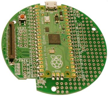
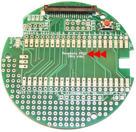
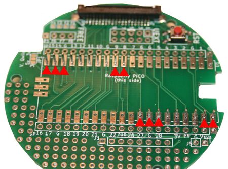
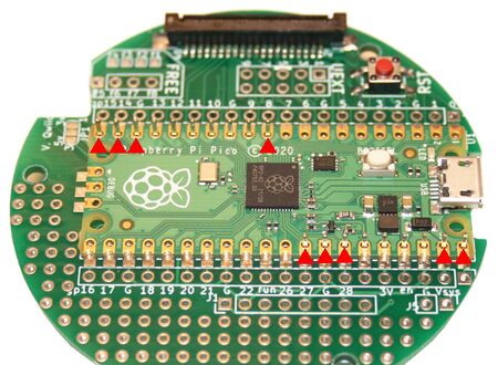
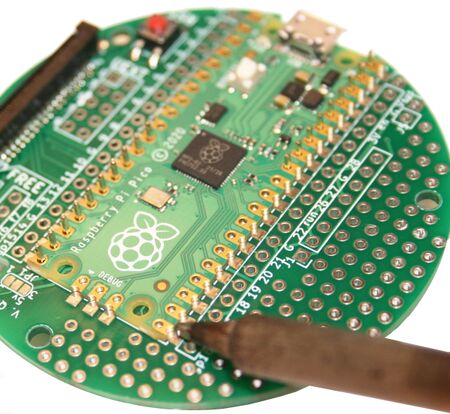
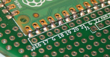
Raspberry-Pi Pico Soldering
The Pico is the MicroControler propeling the board.
It is soldered on the top of the Cansat Base Board, this can be done with Pin Header or directly flat on the board.
Lets starts to assemble it!
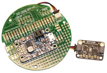
Lipo Booster soldering
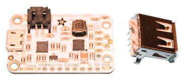
The kit can be used either with a PowerBoost 500 Charger, either a PowerBoost 1000 Charger.
The soldering operation depends on the selected PowerBoost model.
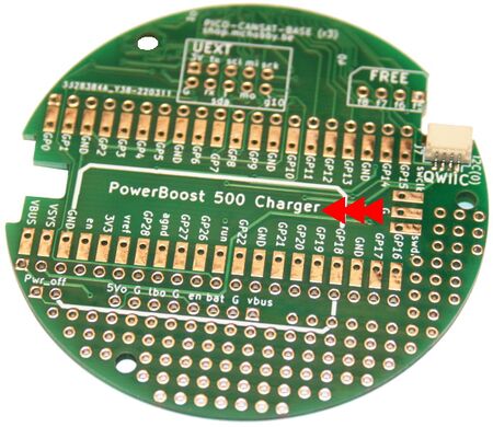
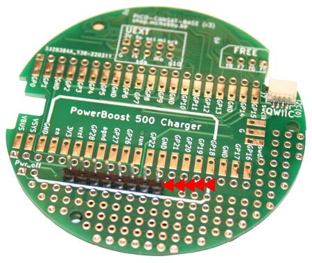
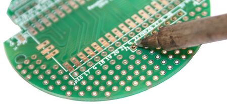
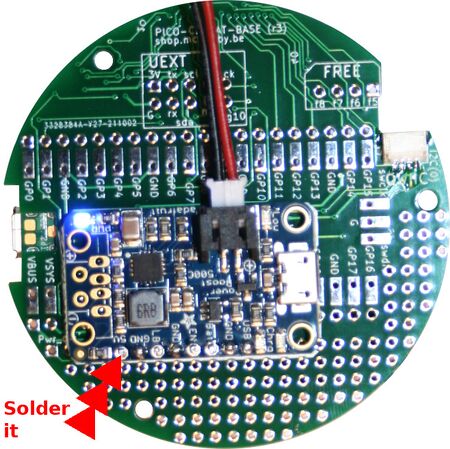
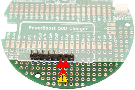
PowerBoost 500 Charger Soldering
The PowerBoost 500 is the default powering system of this kit.
| The instructions doesn't applies to the PowerBoost 1000 charger. |
Let's solder it
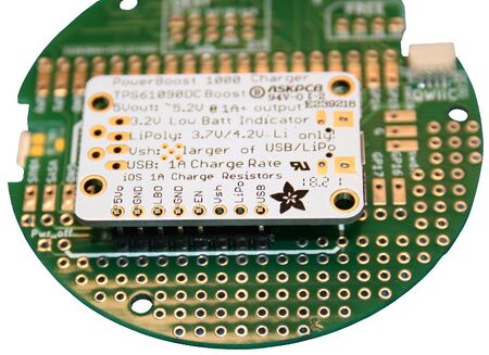
PowerBoost 1000 Charger Soldering
The PowerBoost 500 of the kit can be replaced with a PowerBoost 1000 to get more power (1000mA) from the Lipo battery
| The instructions doesn't applies to the PowerBoost 500 charger. |
Let's solder it
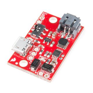
SparkFun Lipo Charger/Booster Soldering
The PowerBoost 500 of the kit can be replaced with a SparkFun Lipo Charger/Booster to get more power (1000mA) from the Lipo battery
| The instructions only applies to the SparkFun Lipo Charger/Booster (PRT-14411). |
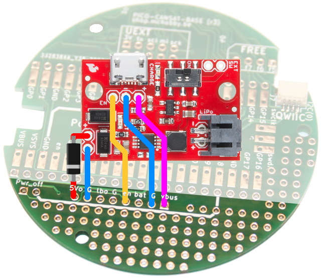
Let's solder it!
Ideally, we should add a Schottky Diode (they are super fast) at the output of the "Lipo Charger/Booster" to avoids back current into the booster when the Pico is connected to a computer.
|
|
The board scwitch must be on ON to power the Cansat from the Lipo. Place it on OFF for long storage period to disconnect the battery from the board. |
| Lipo Charger/Booster |
Cansat Base silkscreen |
PICO pin implied |
Remark |
|---|---|---|---|
| 5V+ | 5Vo | Vsys | Adding a Schottky diode would be great. When the Booster is active, it power-up the Pico through the VSYS pin. |
| 5V- | G | GND | |
| USB+ | VBUS | VBus | Will be at +5V when the pico is wired to a computer. This will |
| USB- | G | GND | |
| EN | En | Will disable the Booster when tied to Ground |
RFM69HCW Soldering
The RFM69HWC is the radio module used in the CanSat-Pico kit to transmit data
| RFM69HCW | UEXT pin | PICO | Remark |
|---|---|---|---|
| RST | GP3 | ||
| CS | GP5 | keep the same pin as receiver. Otherwise use UEXT 10 (=gp10) | |
| MISO | 7 | GP4 = MISO | |
| MOSI | 8 | GP7 = MOSI | |
| SCK | 9 | GP6 = SCK | |
| GND | 2 | PICO GND | |
| VIN | 1 | PICO 3.3V |
Attaching the boards together
You are certainly impatient to attach the boards together with the ribbon.
If the required components are already soldered on the boards then everything is ready to attach the board together otherwise browse up this page to locate the required soldering tasks.
About the FPC connector
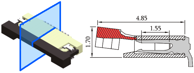
The selected FPC connector us the "Press Fit" technology which is resistant to traction and vibration. Such connectors can even been definitively locked with some glue.
This means than once the ribbon right in place into the connector, you press down the locker to fit/secure the ribbon.
Once secured, the ribbon will not move without releasing the lock.
As show on the section of the connector here under, the ribon is inserted into the connector with contact facing the contact point.
When the moving part is inserted behind the ribon, the ribon contact are pressed onto the contact points. Points that also firmly maintain the ribbon right in place.
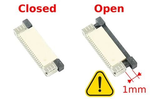
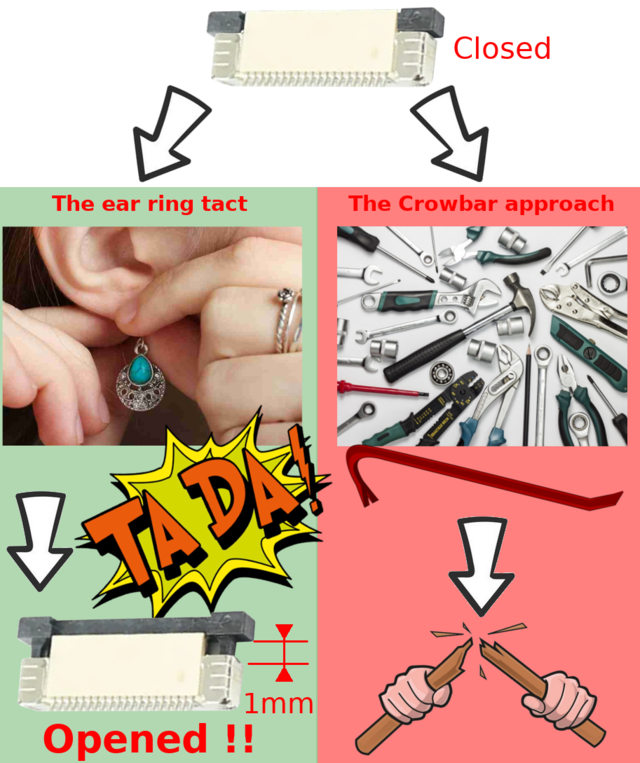
How to manipulate the FPC Connector
The lock slides of 1 millimeter up.
1mm is not a lot but quite enough to secure the ribbon in place.
Attaching the board
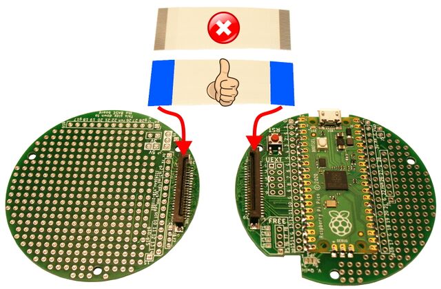
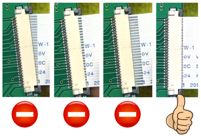
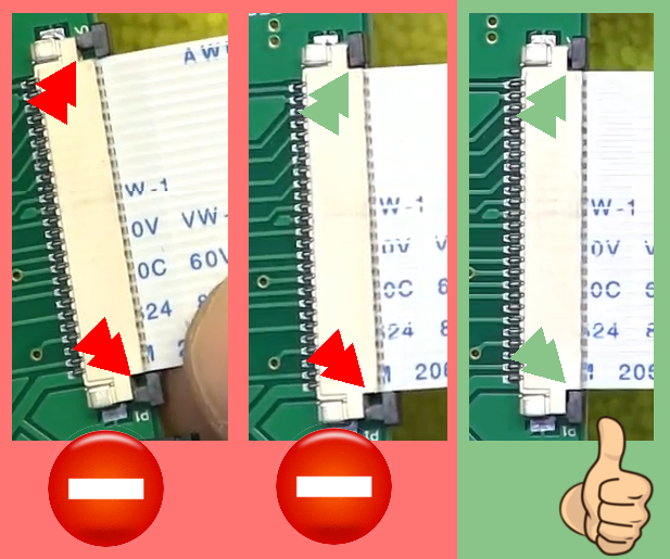
When connecting the ribbon, the electrical contact must be oriented downward.
Ribbon must be inserted straight in the FPC connector
Both side of the of the connector must be pressed down to secure the ribbon. If now properly closed, some signals will not be shipped on the ribbon.
You can also check the "YouTube Video" explaining on to attach the boards.
Written by Meurisse D. for MCHobby
