|
|
| Ligne 1 : |
Ligne 1 : |
| | {{ENG-CANSAT-NAV}} | | {{ENG-CANSAT-NAV}} |
| | | | |
| − | == Forewords ==
| + | {{COMMON-CANSAT-FREQUENCY-PLAN}} |
| − | The RFM69 module and Packet Radio can do a lot to secure message transmission and message content (with the encryption key).
| |
| − | | |
| − | As for wired network (aka TCP/IP) the packet radio enclose your data into datagram before sending it over the air. This helps the hardware to detect error and possibly recover when collisions occurs.
| |
| − | | |
| − | Obviously, more we are talking on a same frequency, more we will have collision, less the communication will be efficient.
| |
| − | | |
| − | The best solution would be to use a frequency plan where each team receives its own frequency range like showed in the following table.
| |
| − | | |
| − | == Suggested Frequency Plan ==
| |
| − | | |
| − | Together with the attributed Frequency, we do recommend the Teams to define their own encryption KEY for radio transmission (this will be clarified further in the documentation).
| |
| − | | |
| − | {| class="wikitable" border="1"
| |
| − | |-
| |
| − | | align="center" | '''Team'''
| |
| − | | align="center" | '''Freq (MHz)'''
| |
| − | | align="center" | '''Team name'''
| |
| − | |- style="font-size: 90%"
| |
| − | | align="left" | Team #1
| |
| − | | align="left" | 433.1
| |
| − | | align="left" | . .
| |
| − | |- style="font-size: 90%"
| |
| − | | align="left" | Team #2
| |
| − | | align="left" | 433.2
| |
| − | | align="left" |
| |
| − | |- style="font-size: 90%"
| |
| − | | align="left" | Team #3
| |
| − | | align="left" | 433.3
| |
| − | | align="left" |
| |
| − | |- style="font-size: 90%"
| |
| − | | align="left" | Team #4
| |
| − | | align="left" | 433.4
| |
| − | | align="left" |
| |
| − | |- style="font-size: 90%"
| |
| − | | align="left" | Team #5
| |
| − | | align="left" | 433.5
| |
| − | | align="left" |
| |
| − | |- style="font-size: 90%"
| |
| − | | align="left" | Team #6
| |
| − | | align="left" | 433.6
| |
| − | | align="left" |
| |
| − | |- style="font-size: 90%"
| |
| − | | align="left" | Team #7
| |
| − | | align="left" | 433.7
| |
| − | | align="left" |
| |
| − | |- style="font-size: 90%"
| |
| − | | align="left" | Team #8
| |
| − | | align="left" | 433.8
| |
| − | | align="left" |
| |
| − | |- style="font-size: 90%"
| |
| − | | align="left" | Team #9
| |
| − | | align="left" | 433.9
| |
| − | | align="left" |
| |
| − | |- style="font-size: 90%"
| |
| − | | align="left" | ...
| |
| − | | align="left" | 434.0
| |
| − | | align="left" | ...
| |
| − | |}
| |
| − | | |
| − | == Frequency plan explained ==
| |
| − | Why do we space the frequencies of 0.1 MHz (so 100 KHz)? Spacing more (>100 KHz) will be best, spacing less (<100 KHz) is not recommended.
| |
| − | | |
| − | The following capture coming from USA shows the spectrum view (and waterfall view) of a RFM69 emiting on the 868.0 MHz frequency. Just remember that it works the same for CanSat around the 433 Mhz.
| |
| − | | |
| − | {{ambox|text=Note: the 868.0 Mhz is a FREE ISM band in USA. In Europe, that frequency range is reserved for LoRa transmission!}} | |
| − | | |
| − | [[Fichier:ENG-CANSAT-FREQUENCY-PLAN-10.png|640px]]<small><br />Source: [https://forum.mysensors.org/topic/11501/rfm69-range-issues this thread in the mysensors.org forum]</small>
| |
| − | | |
| − | This second capture does focus on the interesting part of the picture (spectrum around 868 Mhz and corresponding waterfall).
| |
| − | | |
| − | [[Fichier:ENG-CANSAT-FREQUENCY-PLAN-11.png]]<small><br />Source: [https://forum.mysensors.org/topic/11501/rfm69-range-issues this thread in the mysensors.org forum]</small>
| |
| − | | |
| − | As you can see, the transmission does take place on the right and left side around the central 868.0 MHz axis. A bit like a mirroring image. This is called "Double Side Band" (DSB) communication in the radio area with the carrier wavelength set to 868.0 Mhz.
| |
| − | | |
| − | {{ambox|text=The carrier wavelength doesn't ship any data/information (no peak in that position) since the "Double Side Bands" are enough to rebuild the transmited information.}}
| |
| − | | |
| − | By comparing the spectrum and waterfall (on the right part), we can see the communication take places between 868.0 MHz and 868.030 MHz. This is the same on the opposite side of the picture.
| |
| − | | |
| − | So RFM69 Packet radio transmission takes place between:
| |
| − | * Carrier WaveLength + 30 KHz
| |
| − | * Carrier WaveLength - 30 KHz
| |
| − | So a total of 60 KHz around the carrier Wave length.
| |
| − | | |
| − | {{ambox|text=the waterfall section does show some activities over 30 KHz which is flooded inside the noise (no real peak visible on the spectrum). It is probably some radio emiting harmonics. }}
| |
| − | | |
| − | So, with the starting Carrier Frequency = 433.1 MHz, we would have the following unperfect series: 433.1, 433.16, 433.22, 433.28, and so on. This proposal is unperfect because the transmission spectrums of the proposed frequencies are just "touching" each other.
| |
| − | | |
| − | The best would be to keep some room between the transmissions spectrums, so we could space the frequencies of 80 KHz or even better and simplier 100 KHz!
| |
| − | | |
| − | '''So the suggested frequency plan is 433.1, 433.2, 433.3, 433.4, 433.5''', and so on.
| |
| | | | |
| | {{ENG-CANSAT-TRAILER}} | | {{ENG-CANSAT-TRAILER}} |
Forewords
The RFM69 module and Packet Radio can do a lot to secure message transmission and message content (with the encryption key).
As for wired network (aka TCP/IP) the packet radio enclose your data into datagram before sending it over the air. This helps the hardware to detect error and possibly recover when collisions occurs.
Obviously, more we are talking on a same frequency, more we will have collision, less the communication will be efficient.
The best solution would be to use a frequency plan where each team receives its own frequency range like showed in the following table.
Suggested Frequency Plan
Together with the attributed Frequency, we do recommend the Teams to define their own encryption KEY for radio transmission (this will be clarified further in the documentation).
| Team
|
Freq (MHz)
|
Team name
|
| Team #1
|
433.1
|
. .
|
| Team #2
|
433.2
|
|
| Team #3
|
433.3
|
|
| Team #4
|
433.4
|
|
| Team #5
|
433.5
|
|
| Team #6
|
433.6
|
|
| Team #7
|
433.7
|
|
| Team #8
|
433.8
|
|
| Team #9
|
433.9
|
|
| ...
|
434.0
|
...
|
Frequency plan explained
Why do we space the frequencies of 0.1 MHz (so 100 KHz)? Spacing more (>100 KHz) will be best, spacing less (<100 KHz) is not recommended.
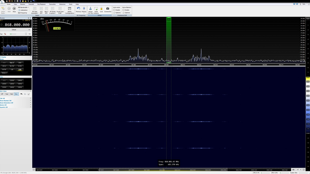
The following capture coming from USA shows the spectrum view (and waterfall view) of a RFM69 emiting on the 868.0 MHz frequency. Just remember that it works the same for CanSat around the 433 Mhz.

Source: this thread in the mysensors.org forum
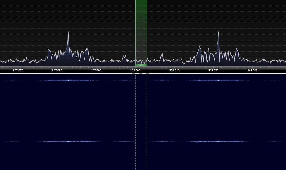
This second capture does focus on the interesting part of the picture (spectrum around 868 Mhz and corresponding waterfall).

Source: this thread in the mysensors.org forum
As you can see, the transmission does take place on the right and left side around the central 868.0 MHz axis. A bit like a mirroring image. This is called "Double Side Band" (DSB) communication in the radio area with the carrier wavelength set to 868.0 Mhz.
By comparing the spectrum and waterfall (on the right part), we can see the communication take places between 868.0 MHz and 868.030 MHz. This is the same on the opposite side of the picture.
So RFM69 Packet radio transmission takes place between:
- Carrier WaveLength + 30 KHz
- Carrier WaveLength - 30 KHz
So a total of 60 KHz around the carrier Wave length.
So, with the starting Carrier Frequency = 433.1 MHz, we would have the following unperfect series: 433.1, 433.16, 433.22, 433.28, and so on. This proposal is unperfect because the transmission spectrums of the proposed frequencies are just "touching" each other.
The best would be to keep some room between the transmissions spectrums, so we could space the frequencies of 80 KHz or even better and simplier 100 KHz!
So the suggested frequency plan is 433.1, 433.2, 433.3, 433.4, 433.5, and so on.
Written by Meurisse D. from MC Hobby - License: CC-SA-BY.

