MicroPython-Hack-servo
Contrôler un Servo moteur
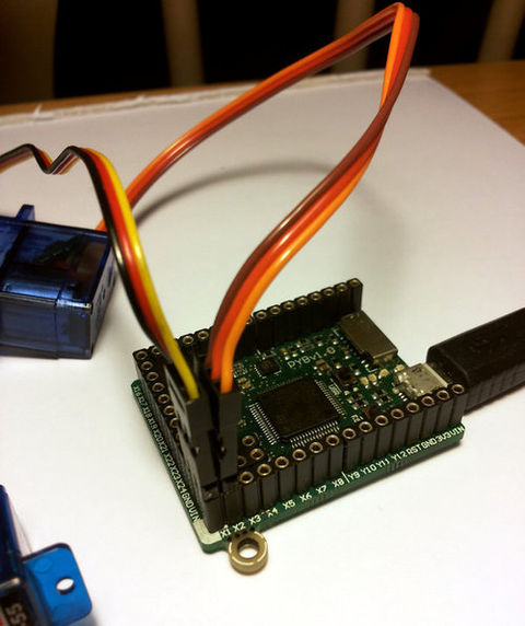
There are 4 dedicated connection points on the pyboard for connecting up hobby servo motors (voyez ce-dessous).
These motors have 3 wires: ground, power and signal. On the pyboard you can connect them in the bottom right corner, with the signal pin on the far right. Pins X1, X2, X3 and X4 are the 4 dedicated servo signal pins.
Qu'est-ce qu'un servo moteur?
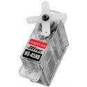
Un servo-moteur est un type de moteur électrique. C'est un dispositif typiquement utilisé en modélisme pour, par exemple, contrôler la direction d'une voiture télécommandée.
Sur un servo-moteur, l'angle de de l'axe reste fixé dans une position et peu varier entre 0 et 180° en fonction du signal envoyé. Un servo-moteur comprend :
- Un moteur électrique (continu), généralement assez petit.
- Des engrenages réducteur en sortie du ce moteur (pour avoir moins de vitesse et plus de couple ou de force).
- Un capteur type "potentiomètre" raccordé sur la sortie.
- Il s'agit donc d'une résistance qui varie en fonction de l'angle, ce qui permet de mesurer l'angle de rotation sur l'axe de sortie.
- Un asservissement électronique pour contrôler la position/rotation, de cet axe de sortie pour le maintenir à la bonne position.
Commander électronique d'un servo-moteur?
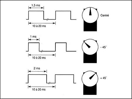
Le principe de base est assez simple. Il suffit d'envoyer une impulsion et c'est le temps que durera cette impulsion qui déterminera l'angle du servo-moteur. ce temps d'impulsion est de quelques de quelques millisecondes et doit être répété à intervalle régulier (toutes les 20 ms à 50ms). Si le temps d'impulsion varie d'un fabricant à l'autre, les valeurs suivantes sont assez standard:
- 1.25 ms = 0 degré
- 1.50 ms = 90 degrés
- 1.75 ms = 180 degrés
Source: Area RC-Bot
Raccordement d'un servo-moteur
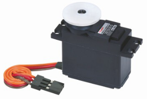
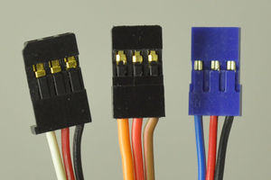
Puisque l'interface de commande est assez simple, un servo-moteur se raccorde avec seulement 3 fils (la masse, +5v et la commande d'impulsion). Les raccordements les plus standardisés sont:
Noir, Rouge, Blanc
- Noir: Raccordé à la Masse,
- Rouge: Alimentation moteur et logique de commande. Raccordé à VCC 5v,
- Blanc: Commande de la position du servo-moteur.
Marron, Rouge, Jaune
Couleurs du standard Graupner.
- Marrons: Raccordé à la Masse,
- Rouge: Alimentation moteur et logique de commande. Raccordé à VCC 5v,
- Jaune: Commande de la position du servo-moteur.
Les autres cas
La plupart des servo-moteur ont 3 conducteurs avec des couleurs noir, rouge et blanc OU brun, rouge et orange/jaune/etc:
- brun ou nour = MASSE/GND (borne négative de l'alimentation)
- Rouge = alimentation servo (Vservo, borne positive de l'alimentation)
- Orange, jaune, blanc ou bleu = Commande de position du servo
Please check the specs for your servo to determine the proper power supply voltage, and please take care to plug the servo into your device in the proper orientation (plugging it in backwards could break the servo or your device).
Brancher un Servo Moteur
In this picture there are male-male double adaptors to connect the servos to the header pins on the pyboard.
The ground wire on a servo is usually the darkest coloured one, either black or dark brown. The power wire will most likely be red.
The power pin for the servos (labelled VIN) is connected directly to the input power source of the pyboard. When powered via USB, VIN is powered through a diode by the 5V USB power line. Connect to USB, the pyboard can power at least 4 small to medium sized servo motors.
If using a battery to power the pyboard and run servo motors, make sure it is not greater than 6V, since this is the maximum voltage most servo motors can take. (Some motors take only up to 4.8V, so check what type you are using.)
Commander un servo-moteur
Plug in a servo to position 1 (the one with pin X1) and create a servo object using:
>>> servo1 = pyb.Servo(1)
To change the angle of the servo use the angle method:
>>> servo1.angle(45)
>>> servo1.angle(-60)
The angle here is measured in degrees, and ranges from about -90 to +90, depending on the motor. Calling angle without parameters will return the current angle:
>>> servo1.angle()
-60
Note that for some angles, the returned angle is not exactly the same as the angle you set, due to rounding errors in setting the pulse width.
You can pass a second parameter to the angle method, which specifies how long to take (in milliseconds) to reach the desired angle. For example, to take 1 second (1000 milliseconds) to go from the current position to 50 degrees, use
>>> servo1.angle(50, 1000)
This command will return straight away and the servo will continue to move to the desired angle, and stop when it gets there. You can use this feature as a speed control, or to synchronise 2 or more servo motors. If we have another servo motor (servo2 = pyb.Servo(2)) then we can do
>>> servo1.angle(-45, 2000); servo2.angle(60, 2000)
This will move the servos together, making them both take 2 seconds to reach their final angles.
Note: the semicolon between the 2 expressions above is used so that they are executed one after the other when you press enter at the REPL prompt. In a script you don’t need to do this, you can just write them one line after the other. 1.2. Continuous rotation servos
Commander servo à rotation continue
So far we have been using standard servos that move to a specific angle and stay at that angle. These servo motors are useful to create joints of a robot, or things like pan-tilt mechanisms. Internally, the motor has a variable resistor (potentiometer) which measures the current angle and applies power to the motor proportional to how far it is from the desired angle. The desired angle is set by the width of a high-pulse on the servo signal wire. A pulse width of 1500 microsecond corresponds to the centre position (0 degrees). The pulses are sent at 50 Hz, ie 50 pulses per second.
You can also get continuous rotation servo motors which turn continuously clockwise or counterclockwise. The direction and speed of rotation is set by the pulse width on the signal wire. A pulse width of 1500 microseconds corresponds to a stopped motor. A pulse width smaller or larger than this means rotate one way or the other, at a given speed.
On the pyboard, the servo object for a continuous rotation motor is the same as before. In fact, using angle you can set the speed. But to make it easier to understand what is intended, there is another method called speed which sets the speed:
>>> servo1.speed(30)
speed has the same functionality as angle: you can get the speed, set it, and set it with a time to reach the final speed.
>>> servo1.speed()
30
>>> servo1.speed(-20)
>>> servo1.speed(0, 2000)
The final command above will set the motor to stop, but take 2 seconds to do it. This is essentially a control over the acceleration of the continuous servo.
A servo speed of 100 (or -100) is considered maximum speed, but actually you can go a bit faster than that, depending on the particular motor.
The only difference between the angle and speed methods (apart from the name) is the way the input numbers (angle or speed) are converted to a pulse width.
Calibration
The conversion from angle or speed to pulse width is done by the servo object using its calibration values. To get the current calibration, use
>>> servo1.calibration()
(640, 2420, 1500, 2470, 2200)
There are 5 numbers here, which have meaning:
- Minimum pulse width; the smallest pulse width that the servo accepts.
- Maximum pulse width; the largest pulse width that the servo accepts.
- Centre pulse width; the pulse width that puts the servo at 0 degrees or 0 speed.
- The pulse width corresponding to 90 degrees. This sets the conversion in the method angle of angle to pulse width.
- The pulse width corresponding to a speed of 100. This sets the conversion in the method speed of speed to pulse width.
You can recalibrate the servo (change its default values) by using:
>>> servo1.calibration(700, 2400, 1510, 2500, 2000)
Of course, you would change the above values to suit your particular servo motor.
Source: Controling Hobby Servo écrit par/written by Damien P.George
Traduit et augmenté par Meurisse D. pour MCHobby.be - Translated and upsized by Meurisse D. for MCHobby.be
Traduit avec l'autorisation de micropython.org - Translated with the authorisation of micropython.org
Toute référence, mention ou extrait de cette traduction doit être explicitement accompagné du texte suivant : « Traduction par MCHobby (www.MCHobby.be) - Vente de kit et composants » avec un lien vers la source (donc cette page) et ce quelque soit le média utilisé.
L'utilisation commercial de la traduction (texte) et/ou réalisation, même partielle, pourrait être soumis à redevance. Dans tous les cas de figures, vous devez également obtenir l'accord du(des) détenteur initial des droits. Celui de MC Hobby s'arrêtant au travail de traduction proprement dit.
Servo à rotation continue
So far we have been using standard servos that move to a specific angle and stay at that angle. These servo motors are useful to create joints of a robot, or things like pan-tilt mechanisms. Internally, the motor has a variable resistor (potentiometer) which measures the current angle and applies power to the motor proportional to how far it is from the desired angle. The desired angle is set by the width of a high-pulse on the servo signal wire. A pulse width of 1500 microsecond corresponds to the centre position (0 degrees). The pulses are sent at 50 Hz, ie 50 pulses per second.
You can also get continuous rotation servo motors which turn continuously clockwise or counterclockwise. The direction and speed of rotation is set by the pulse width on the signal wire. A pulse width of 1500 microseconds corresponds to a stopped motor. A pulse width smaller or larger than this means rotate one way or the other, at a given speed.
On the pyboard, the servo object for a continuous rotation motor is the same as before. In fact, using angle you can set the speed. But to make it easier to understand what is intended, there is another method called speed which sets the speed:
>>> servo1.speed(30)
speed has the same functionality as angle: you can get the speed, set it, and set it with a time to reach the final speed.
>>> servo1.speed() 30 >>> servo1.speed(-20) >>> servo1.speed(0, 2000)
The final command above will set the motor to stop, but take 2 seconds to do it. This is essentially a control over the acceleration of the continuous servo.
A servo speed of 100 (or -100) is considered maximum speed, but actually you can go a bit faster than that, depending on the particular motor.
The only difference between the angle and speed methods (apart from the name) is the way the input numbers (angle or speed) are converted to a pulse width. 1.3. Calibration
The conversion from angle or speed to pulse width is done by the servo object using its calibration values. To get the current calibration, use
>>> servo1.calibration() (640, 2420, 1500, 2470, 2200)
There are 5 numbers here, which have meaning:
   Minimum pulse width; the smallest pulse width that the servo accepts.
   Maximum pulse width; the largest pulse width that the servo accepts.
   Centre pulse width; the pulse width that puts the servo at 0 degrees or 0 speed.
   The pulse width corresponding to 90 degrees. This sets the conversion in the method angle of angle to pulse width.
   The pulse width corresponding to a speed of 100. This sets the conversion in the method speed of speed to pulse width.
You can recalibrate the servo (change its default values) by using:
>>> servo1.calibration(700, 2400, 1510, 2500, 2000)
Of course, you would change the above values to suit your particular servo motor.
Source: Controling Hobby Servo écrit par/written by Damien P.George
Traduit et augmenté par Meurisse D. pour MCHobby.be - Translated and upsized by Meurisse D. for MCHobby.be
Traduit avec l'autorisation de micropython.org - Translated with the authorisation of micropython.org
Toute référence, mention ou extrait de cette traduction doit être explicitement accompagné du texte suivant : « Traduction par MCHobby (www.MCHobby.be) - Vente de kit et composants » avec un lien vers la source (donc cette page) et ce quelque soit le média utilisé.
L'utilisation commercial de la traduction (texte) et/ou réalisation, même partielle, pourrait être soumis à redevance. Dans tous les cas de figures, vous devez également obtenir l'accord du(des) détenteur initial des droits. Celui de MC Hobby s'arrêtant au travail de traduction proprement dit.

