ENG-CANSAT-CONTENT
Feather M0 Express in few words
The CanSat kit it build around the Adafruit Industries Feather M0 Express plateform.
- Feather is a new emerging standard -Arduino compatible plaform- for embedded projet.
- Feather is small, light and already brings lot useful features.
- Feather M0 is compatible with Arduino M0, so compatible with Arduino IDE.
- Feather M0 Express also embed FLASH memory that can act like SD Card (Arduino IDE) or USB Stick (CircuitPython)
| Feather M0 Features |
| 20 GPIOs |
| 6 Analog inputs 12bits value from 0 to 4095. |
| 1 Analog output 10 bits value from 0 to 1023. |
| PWM on all pins |
| Hardware I2C et SPI buses |
| UART |
| Feather are: |
| * Small (5c2xm) |
| * Light (4.7Gr) |
| * Powerful |
| * Versatile |
| * Polyvalent |
| * Available with complete ecosystem |
Kit content
| Description | Quantité | |
Feather M0 Express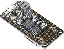
|
New Arduino M0 compatible on a standard platform for embedded project. Also compatible with CircuitPython. disponible ici chez MCHobby |
1 |
USB A/microB 1m cable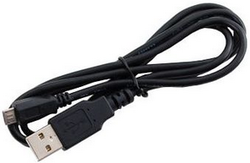
|
Can be used to plug your feather on a computer to program it or to reload the Lipo. disponible ici chez MCHobby |
1 |
Half Size Breadboard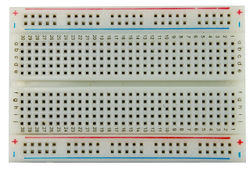
|
Solderless breadboard are used for fast prototyping. disponible ici chez MCHobby |
1 |
Multi-functional breadboard wires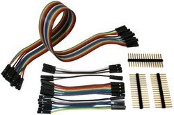
|
Set of wires with plug that can be modified from female to male. disponible ici chez MCHobby |
1 |
Feather Stacking Headers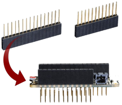
|
Plug your feather or prototype wing on breadboard and still having a female connector under the hand. disponible ici chez MCHobby |
1 |
Feather Prototyping Wing
|
Prototyping board for feather platform. Create your own extension board (wing) by soldering connectors and components. disponible ici chez MCHobby |
1 |
Lithium Polymer Battery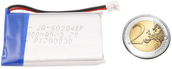
|
Transform the Feather into an autonomous plateform with this 800mAh Lipo. disponible ici chez MCHobby |
1 |
BMP280 – Barometric pressure sensor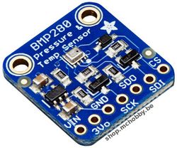
|
Easily evaluate pressure, altitude and temperature. disponible ici chez MCHobby |
1 |
TMP36 – analog temperature sensor
|
Transform the sensor voltage read on analog input into an easy-to-read temperature. disponible ici chez MCHobby |
1 |
RFM69HCW Transceiver Radio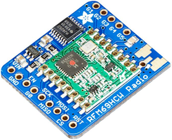
|
Transport data over long distance with packet radio. One breakout act as emitter, the second one as receiver. disponible ici chez MCHobby |
2 |
Feather M0 Express in details
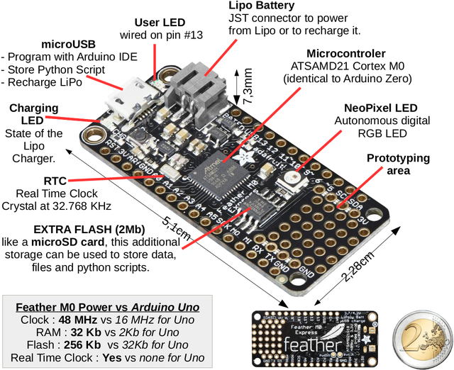
The Feather M0 use the ATSAMD21G18 ARM Cortex M0+ processor with 3.3V logic and 48 MHz. This chip embed 256K of FLASH (8x more than the Atmega328/Uno) and has 32K RAM (16x more than UNO)!
This ATSAMD21G18 has USB built-in which offers USB-to-Serial and debug feature (so no need for FTDI-like chip).
The feather has the following specs:
- Size: 51mm x 23mm x 8mm
- Weight: 5 grams
- ATSAMD21G18 @ 48MHz
- 3.3V logic/power
- 256KB of FLASH
- 32KB of RAM
- No EEPROM
- RTC & Clock based on 32.768 KHz crystal
- 3.3V regulator (500mA peak current) with Power/enable pin
- USB native support (has USB bootloader)
- 20 GPIO pins (PWM on all pins)
- Hardware Serial + Hardware I2C + Hardware SPI support
- 6 x 12-bit analog inputs (from 0 to 4095)
- 1 x DAC 10-bit analog ouput (from 0 to 1024)
- Lipo Charger included: 100mA charging with status LED
- Red LED attached on pin #13 (like Arduino UNO)
- Reset button
- Mini NeoPixel
- 2 MB SPI additional Flash storage.
About the additionnal Flash:
The SPI Flash storage act like a tiny hard drive.
- Under CircuitPython, the 2 MB Flash is used to the Python scripts, libraries and other files.
- With Arduino, the 2 MB Flash is used to read/write files to it (like a SD card). Adafruit has helper program to access those files over USB.
The UF2 bootloader:
The Feather M0 is pre-loaded with an UF2 bootloader which looks like a USB Flash Drive. Simply drag an UF2 firmware on the USB Flash drive to completely reprogram de board firmware (No special tools, No special drivers needed)! The UF2 bootloader can be used to load up CircuitPython, MakeCode PXT file or Arduino IDE (bossa-compatible).
Feather M0 Express PINOUT
Introduction
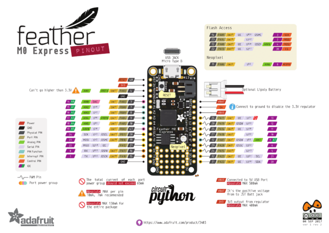
Crédit: AdaFruit Industries www.adafruit.com
Click to enlarge
(Please note that AREF is PA03 (and not PA02)
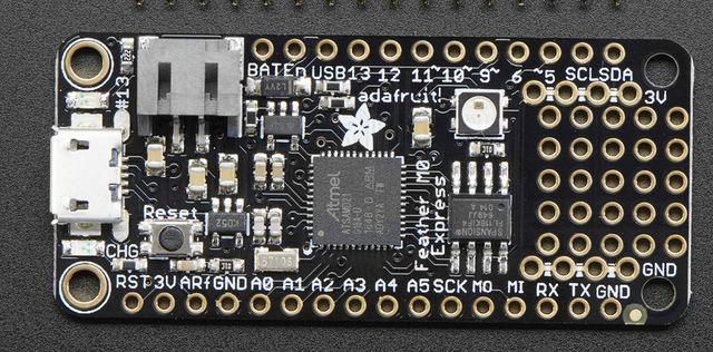
Crédit: AdaFruit Industries www.adafruit.com
The Feather M0 benefits from the Cortex M0 microcontroler hardware. If has many buses and many pins. Let's review them togheter!
Power Pin
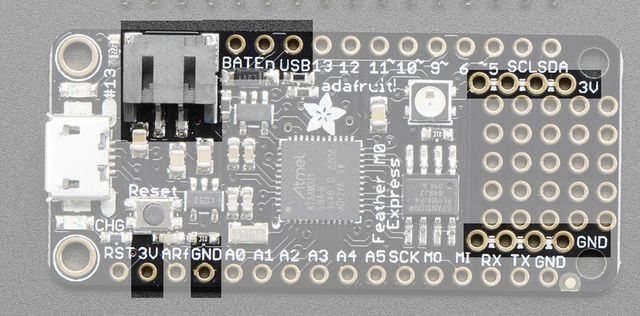
Crédit: AdaFruit Industries www.adafruit.com
- GND : is the common ground. The 0v reference voltage for all the logic and power supplies.
- BAT : positive pin from the JST connector (the optional Lipo).
- USB : positive pin from the USB connector. Will allow you to detect if the board is connected on USB.
- EN : Enable pin of the 3.3V regulator. This pin has a Pull-Up résistor. Connect the EN pin to the ground will shutdown the 3.3V regulator.
- 3V : Output of the 3.3V regulator (500mA peak)
Logical pins
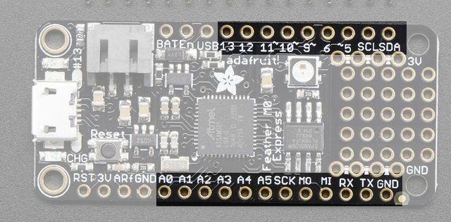
Crédit: AdaFruit Industries www.adafruit.com
This concerns all the I/O pins on the microcontroler.
- Almost all pins can generate PWM signal (also called "analog output" on Arduino UNO board).
- All pins can be used for Interrupt Request (IRQ).
The following pins have specific features:
- #0 / RX - GPIO #0, also receiving pin of the Serial1 UART (hardware serial port, input). Also an analog input.
- #1 / TX - GPIO #1, also transmitting pins of the Serial1 UART (hardware serial port, output). Also an analog input.
- SDA - Data pin for the I2C bus. There is no pull-up resistor on that pin, so you need to add a 2.2K-10K pull-up when used for I2C bus.
- SCL - Clock pin for the I2C bus. There is no pull-up resistor on that pin, so you need to add a 2.2K-10K pull-up when used for I2C bus.
- #5 - GPIO #5
- #6 - GPIO #6
- #9 - GPIO #9, also analog input A7. This analog input is wired on a divider resistor bridge to read the Lipoly battery voltage. As a consequence, the voltage of that pin is fixed to a voltage around ~2V.
- #10 - GPIO #10
- #11 - GPIO #11
- #12 - GPIO #12
- #13 - GPIO #13, also connected to the red LED near if the microUSB située près du connecteur micro USB.
- A0 - Analog input A0 and also a real Analog output since the DAC is wired on this pin (DAC = Digital to Analog Converter). The output voltage can be set with a value from de sortie à une valeur située entre 0 et 3.3V. Au contraire d'une sortie PWM, cette broche est une vraie sortie analogique.
- A1 à A5 - Chacune de ces broches est une entrée analogique, également une broche d'entrée/sortie.
- SCK/MOSI/MISO - Ce sont les broches du bus SPI matériel, également utilisable comme broche d'entrée/sortie. Nous recommandons de préserver ces broches car le bus SPI matériel permet d'atteindre des débit très importants (particulièrement intéressant pour les écrans TFT).
Mémoire Flash SPI et NeoPixel
De surcroît, la série 'Express' de la gamme Feather est conçu pour aussi utilisée avec CircuitPython. Pour faciliter les choses, Adafruit à ajouté deux éléments supplémentairessur ce Feather M0: un mini NéoPixel (LED RGB digitale) et une mémoire flash de 2 MB (sur un bus SPI).
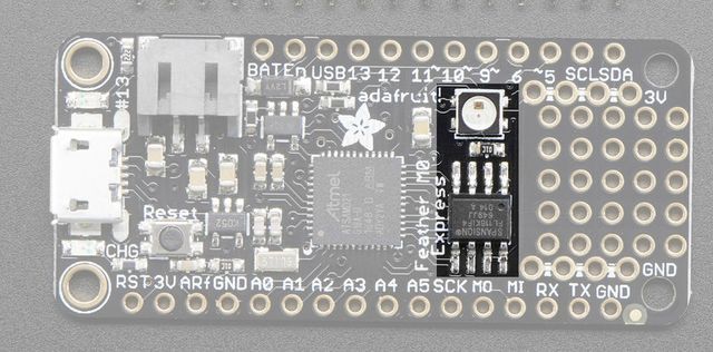
Crédit: AdaFruit Industries www.adafruit.com
La LED NéoPixel est connectée sur le broche #8 ien Arduino, vous pouvez donc utiliser le bibliothèque NéoPixel en configurant un ruban de LED avec une seule LED. Le NéoPixel est alimenté en 3.3V mais cela n'a pas vraiment d'impact sur la couleur ou la luminosité.
NéoPixel
Le NéoPixel est également utilisé par le bootloader pour vous informer de l'état du bootloader:
- Vert : le périphérique à été énuméré correctement sur l'interface USB
- Rouge : erreur USB .
En CircuitPython, la LED est utilisée pour indiquer le statut de fonctionnement.
La Flash SPI
La mémoire Flash SPI est connectée sur 4 broches qui n'ont pas été rendue accessibles en tant que GPIO. De sorte, il n'est pas nécessaire de s'inquiéter d'un éventuel risque de collision avec d'autres périphériques présents sur le bus SPI principal.
Sous Arduino
Les broches de la FLASH sont:
- SCK = broche #3,
- MISO = broche #2,
- MOSI = broche #4
- CS = broche #38.
Sur le Feather M0 Express vous serez capable d'accéder au port de la Flash SPI sous SPI1 - c'est un nouveau périphérique SPI matériel totalement séparé des broches GPIO accessibles à la périphérie de la carte Feather.
Dans le cadre d'une utilisation sous Arduino, cette mémoire Flash SPI permet des opérations de lecture/écriture.
Sous CircuitPython
Sous CircuitPython (MicroPython), la mémoire Flash SPI est nativement utilisée par l'interpréteur Python. Cette mémoire Flash apparaît comme étant en lecture seule pour le code utilisateur.
Autres broches!
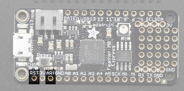
Crédit: AdaFruit Industries www.adafruit.com
- RST - broche de réinitialisation (dite "Reset"). Brancher cette broche à la masse réinitialise le microcontroleur et lance le bootloader.
- ARef - broche "analog reference", référence de tension pour les broches analogique. Par défaut, la tension de référence est identique au niveau logique du composant (soit 3.3v). Il est cependant possible d'utiliser une tension de référence analogique différente (par ex: 1.5V) et d'indiquer dans votre programme qu'il faut utiliser la référence AREF EXTERNE. Dans pareil cas, la lecture 12bit d'une entrée analogique (valeur de 0 à 4095) couvrira une tension d'entrée de 0 à 1.5V. La tension de référence ne peut jamais dépasser 3.3v. La tension sur une broche analogique ne peut pas être supérieur à la tension de référence!
Debug Interface
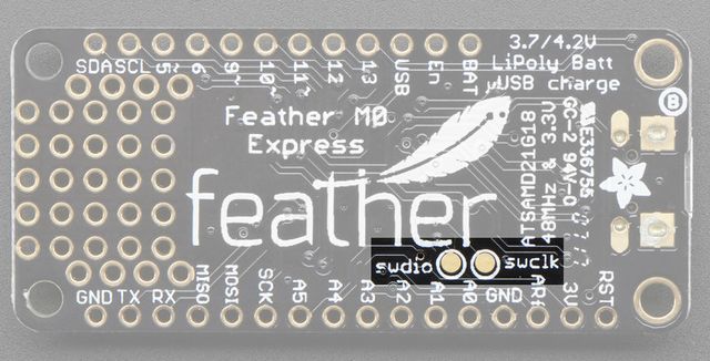
Crédit: AdaFruit Industries www.adafruit.com
- SWCLK et SWDIO - ces pastilles, visibles sous la carte, sont utilisées pour programmer le microcontroleur. Ces pastilles permettent également de connecter un débogueur SWD.
Written by Meurisse D. from MC Hobby - License: CC-SA-BY.
