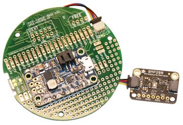
ENG-CANSAT-V2-ASSEMBLY

De MCHobby - Wiki
Sauter à la navigation Sauter à la recherche

Abstract

The original version of the CANSAT kit required many soldering operation. It's intimidating for newcomers with little experience with a soldering iron.

With the CANSAT V2 kit, things have been made easier than ever, no solder required!

Assembling the Cansat

Let's prepare the main CANSAT board.
ENG-CANSAT-V2-CONTENT-10.jpg

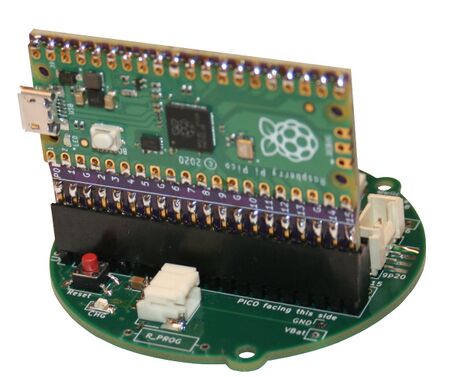
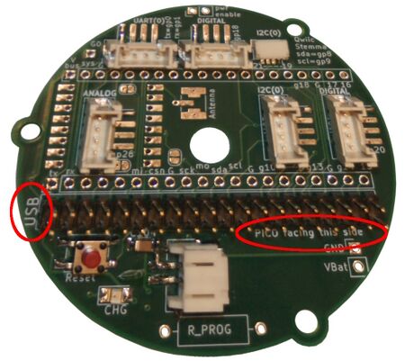
ENG-CANSAT-V2-ASSEMBLY-10.jpg Take the base board and orient the board to see the USB label on the left and the "Pico/MCU facin this side" in front of you.
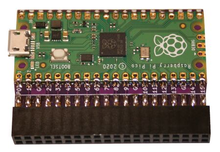
ENG-CANSAT-V2-ASSEMBLY-11.jpg Grab the CPU board with the microcontroler facing front.
ENG-CANSAT-V2-ASSEMBLY-12.jpg Now, insert the MCU board onto the 2x20 pin connector.
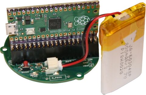
450px Even when not required yet, user can pick the Lipo battery then plug it into the 2 poles JST connector (facing the microcontroler).
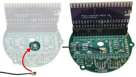
ENG-CANSAT-V2-ASSEMBLY-14.jpg When required, plug the µFl antenna coax.


Lipo Booster soldering

The kit can be used either with a PowerBoost 500 Charger, either a PowerBoost 1000 Charger.

The soldering operation depends on the selected PowerBoost model.

ENG-CANSAT-PICO-05b.jpg

PowerBoost 500 Charger Soldering

The PowerBoost 500 is the default powering system of this kit.

ENG-CANSAT-PICO-02.jpg

Let's solder it

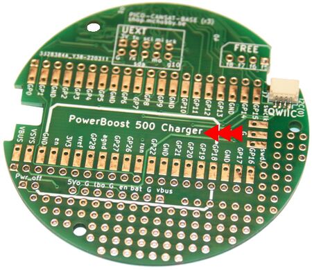
ENG-CANSAT-PICO-20.jpg Pico up the base board with the back of the board on the desk.

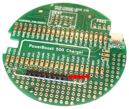
You should see Qwiic connector and the text "PowerBoost 500 Charger" written.

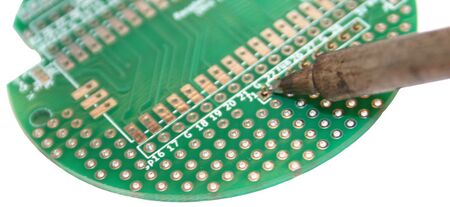
ENG-CANSAT-PICO-21.jpg Place a section of 8 pins into the connector (the short part into the connector).

Tip: use a small piece a paper tape to maintain the connector right in place.

ENG-CANSAT-PICO-22.jpg Flip over the board and solder the connector in place.
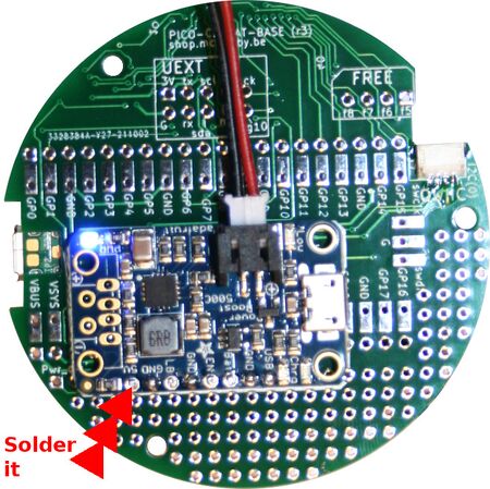
ENG-CANSAT-PICO-23.jpg Flip the board again (to see the "PowerBoost" text).

Slides the PowerBoost 500 on the connector, Solder it and cut-out the pin near of the board (with a diagonal cutter).

WARNING: Electronic components must be visible on the breakout!

Tip:

  • Push on the PowerBoost breakout with the nail against the connector.
    This will flatten the breakout on the connector (and make it paralleled to the base board).
  • Charge the tip of the iron with some solder.
  • Tack a drop of solder on one pin to make the breakout staying right in place (no need to be perfect right now)
  • Solder the other pins of the breakout
  • Now solder the initial tacked pin (to have a nice & great solder join on that pin too)


Written by Meurisse D. for MCHobby

MCHobby investit du temps et de l'argent dans la réalisation de traduction et/ou documentation. C'est un travail long et fastidieux réalisé dans l'esprit Open-Source... donc gratuit et librement accessible.
SI vous aimez nos traductions et documentations ALORS aidez nous à en produire plus en achetant vos produits chez MCHobby.