ENG-CANSAT-V2-CONTENT
Cansat V2 kit in few words
The CanSat-V2-Kit is build around the Raspberry-Pi Pico plateform.
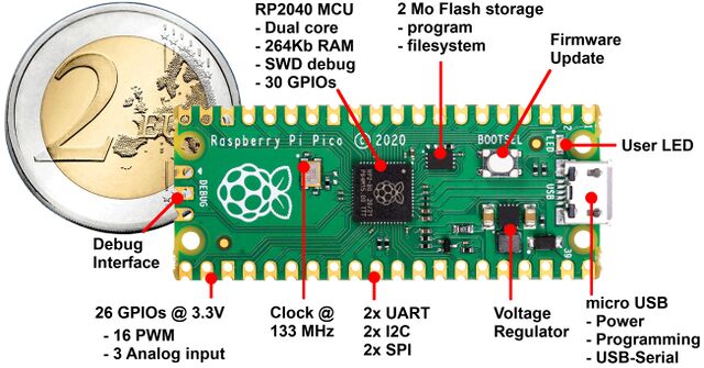
The Raspberry-Pi Pico is a powerful dual core microcontroller created by the Raspberry-Pi foundation.
The Pico goes far beyond the Arduino Uno in terms of power and capabilities.
It is distributed with the MicroPython firmware but can also be programmed with C++ and Arduino.
MicroPython is a very robust environment natively compiling and running python script on microcontroller. MicroPython fits a compiler, a python virtual machine and a file system to store the scripts. Thanks to MicroPython, everything learned with Python language or any MicroPython boards can be applied to the Pico.
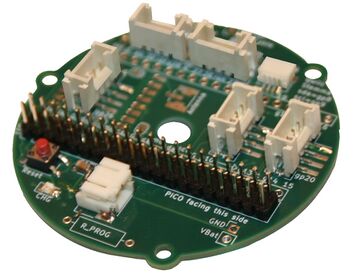
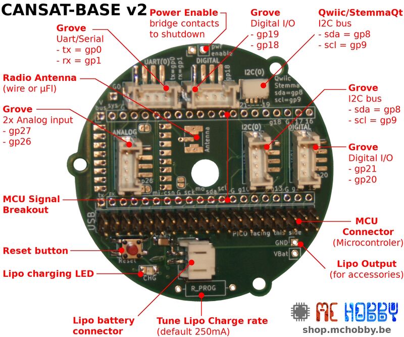
The Cansat-V2 is built around CANSAT-V2-BASE a pre-assembled board featuring:
- Lipo battery charger
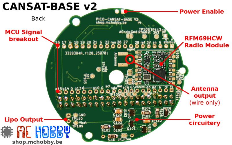
- Radio module
- 3V 600 mA voltage regulator power enable to switch off the Power.
- Plug-able microcontroler/nano-computer board (namely the MCU board)
- Connectors for I2C bus, Serial/UART, Digital I/O, Analog inputs
- Breakout of all MCU signals (offering additional I/O to your project).
- Pre-solder connector antenna (and set of antenna for testing).
Retro Compatibility
Despite obvious visual changes, the CANSAT V2 kit is backwards compatible with the previous version.
The same Pins are used to control the same material.
Electronic Aspect
The kit is designed to ease the prototyping thanks to the well known connectors:
- Grove connectors : supporting 3V3 compatible SeeedStudio sensors and M5Stack sensors (all compatible 3V3).
- Qwiic/StemmaQt : which is I2C bus only. Supporting the Adafruit Industries StemmaQt sensors and SparkFun Qwiic sensors. thanks to Grove-to-Male wires.
- StemmaQT sensors are available at Adafruit Industries USA and its distributor network.
- Qwiic sensors are available at SparkFun electronic USA and its distributor network.
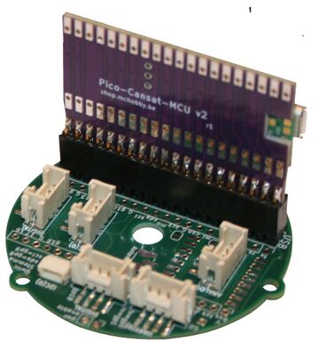
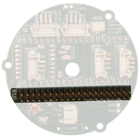
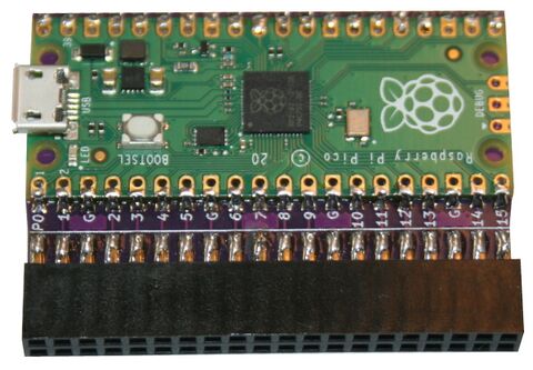
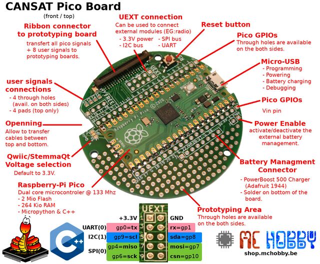
The "Cansat V2 Board" features a MCU board connector where to plug the MCU board.
Remark: the MCU board must be oriented with the USB connector toward the "USB" word on the silkscreen.
Presently, only the Pico MCU board is available, alternative MCU board will exists in the future.
Many of the Pin of Pico are available on Grove connectors.
All the pins of the Pico are broken out to the CANSAT-BASE.
The Pinout description and Schematics will provide lot of useful information.
About Raspberry-pi Pico
The Raspberry-Pi Pico is at the earth of this kit. One is soldered onto the Cansat MCU sub-Kit, the other is free for use to make prototyping or creating the receiving base station.
See the Cansat Pico User Guide section for more information on its integration.
See the Official Pico MicroPython starter guide for learning more about MicroPython on Pico.
Mechanical Aspect
When the kit was designed, we did foreseen the fact that the project could be assembled in many way.
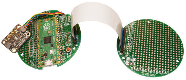
The CANSAT-BASE is accompagned of several other board designed to quickly create the CanSat structure.
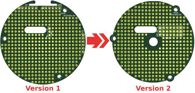
The following picture shows the mechanical evolution of CANSAT-LETTUCE from version 1 to version 2.
As you may notice it:
- The 3 external fixing points stays the same than version 1.
- The general diameter reduced to 60mm (instead of 64mm) leaving more room for 3D Print wall.
- The 6.4mm central hole accross all the CanSat V2 boards to build a central reinforcement column.
More information about mechanical in the Dimensions page
- placed between the boards (inside).
- placed ouside of the boards and use a shorter ribbon (boards are enclosed right in the middle of the project).
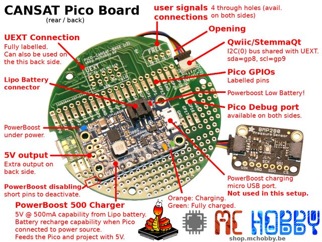
We did also features a Qwiic/StemmaQt connector available underside. This very compact connector do features power and I2C bus. It can be used to quickly and safely connects toons of I2C capable sensors boards.
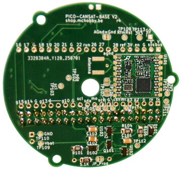
Just flip over the "Cansat Pico Board" to discover additional features available underside the Pico.
As we can propotype under the board, it is also very important to have the board fully labelled this side.
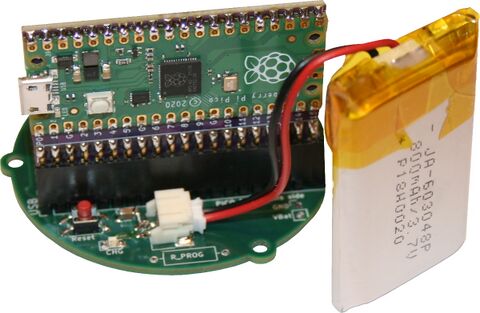
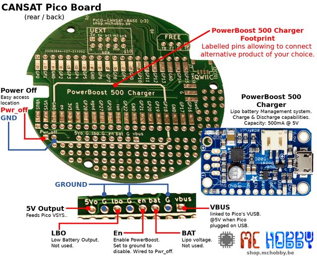
As the Raspberry-Pi Pico doesn't features Lipo battery circuitery, we do added a special connector to plug an Adafruit PowerBoost 500 charger on the board.
Just connect the Pico to you computer (or power it with a wall adapter) and the Lipo will auto-magically starts to charge-up.
Unplug your pico from computer and the PowerBoost charger will take over. The Lipo will discharge to power your project.
Thanks to the PowerBoost, your cansat projet do also have a 5V power rail (500 mA max).
Needs to spare energy? no problem, the "Power Off" pin is available near of the board boundary. Once the PWR_OFF tied to the ground, the PowerBoost is disabled (as Pico and the project).
Cansat V2 Pico Kit content
The Cansat Pico Kit is designed to be compact, evolutive, customisable, sizable (in height) and programmed in Python (thank to MicroPython).
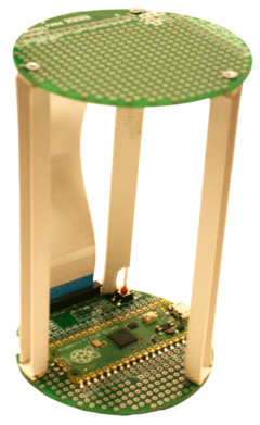
Once assembled with spacer you designed, you do have a cylindrical development plateform with plenty of space.
You can develop your project:
- either in the inner space between the bottom and the top boards.
- either using smaller spacers to develop your project in the inner space and also the outer space.
Outer space can also be used thanks to the through holes PCBs and the labelling the both sides of the PCBs.
Kit content
| Description | Quantité | |
Raspberry-Pi Pico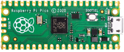
|
Dual core RP2040 MCU @ 133 MHz with 264Ko RAM & 2 Mo Flash. One Pico is used on the Cansat kit, the other is used for prototyping. disponible ici chez MCHobby |
2 |
Cansat base dev. board for Pico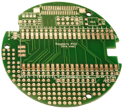
|
Solder a Pico onto it and drive your cansat project with MicroPython. disponible ici chez MCHobby |
1 |
Cansat proto board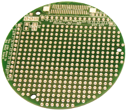
|
Prototyping board connected to the Pico GPIO. disponible ici chez MCHobby |
1 |
FPC ribbon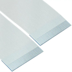
|
This ribbon connects the base board to the proto board. disponible ici chez MCHobby |
1 |
USB A/microB 1m cable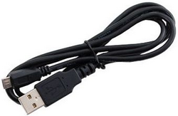
|
Can be used to plug your pico on a computer to program it or to reload the Lipo. disponible ici chez MCHobby |
1 |
Half Size Breadboard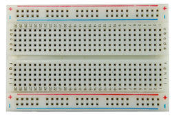
|
Solderless breadboard are used for fast prototyping. disponible ici chez MCHobby |
1 |
Multi-functional breadboard wires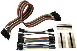
|
Set of wires with plug that can be modified from female to male. disponible ici chez MCHobby |
1 |
PowerBoost 500 charger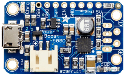
|
Convert a Lipo battery power into usable 5V power source. This board can also reload the Lipo when the kit is powered via USB. disponible ici chez MCHobby |
1 |
Alternative to Powerboost 500 charger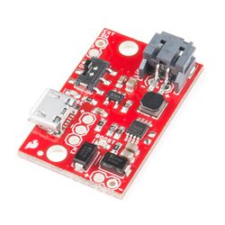
|
Also convert Lipo battery power into usable 5V power. This board can also reload the Lipo when the Kit is powered via USB. disponible ici chez MCHobby |
0 |
Lithium Polymer Battery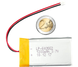
|
Transform the Feather into an autonomous plateform with this 1300mAh Lipo. disponible ici chez MCHobby |
1 |
JST-SH fast connexion wire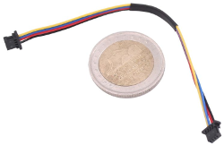
|
This 100mm wire can be used to connect Qwiic or StemmaQt board to the Pico in a snap disponible ici chez MCHobby |
1 |
BMP280 – Barometric pressure sensor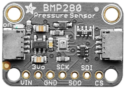
|
Easily evaluate pressure, altitude and temperature. This board expose a StemmaQt connector disponible ici chez MCHobby |
1 |
TMP36 – analog temperature sensor
|
Transform the sensor voltage read on analog input into an easy-to-read temperature. disponible ici chez MCHobby |
1 |
RFM69HCW Transceiver Radio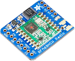
|
Transport data over long distance with packet radio. One breakout act as emitter, the second one as receiver. disponible ici chez MCHobby |
2 |
Written by Meurisse D. for MCHobby

