ENG-CANSAT-V2-ASSEMBLY

De MCHobby - Wiki
Sauter à la navigation Sauter à la recherche

Abstract

The original version of the CANSAT kit required many soldering operation. It's intimidating for newcomers with little experience with a soldering iron.

With the CANSAT V2 kit, things have been made easier than ever, no solder required!

Assembling the Cansat

Let's prepare the main CANSAT board.

ENG-CANSAT-V2-CONTENT-10.jpg

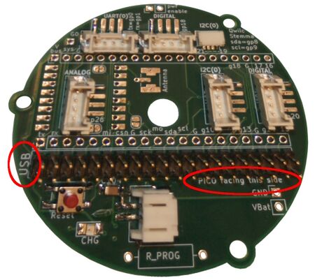
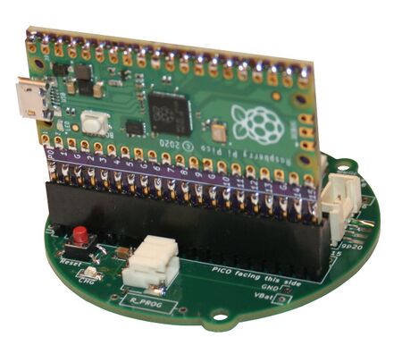
ENG-CANSAT-V2-ASSEMBLY-10.jpg Take the base board and orient the board to see the USB label on the left and the "Pico/MCU facing this side" in front of you.
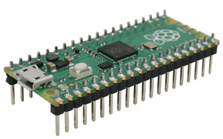
ENG-CANSAT-V2-ASSEMBLY-11.jpg Grab the CPU board with the microcontroler facing front.
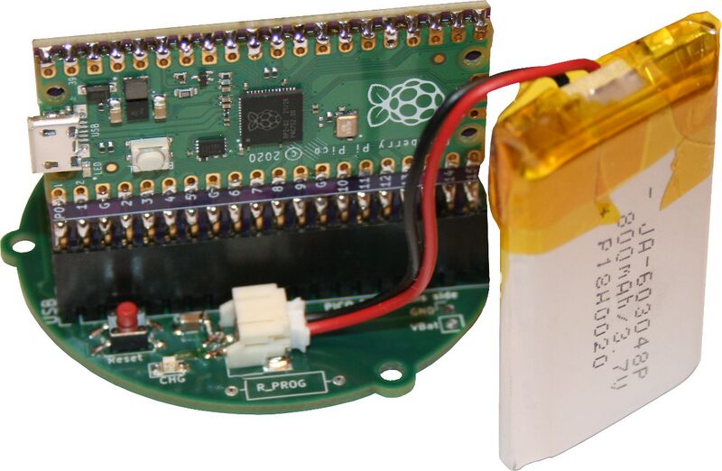
ENG-CANSAT-V2-ASSEMBLY-12.jpg Now, insert the MCU board onto the 2x20 pin connector.
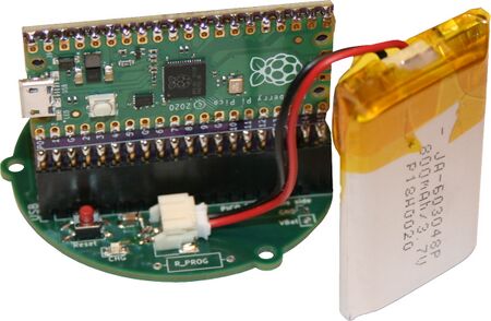
ENG-CANSAT-V2-CONTENT-10.jpg Even when not required yet, user can pick the Lipo battery then plug it into the 2 poles JST connector (facing the microcontroler).
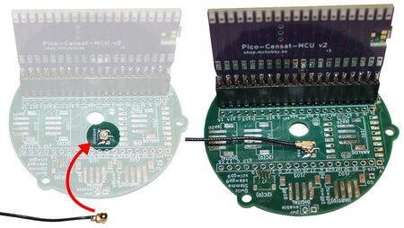
ENG-CANSAT-V2-ASSEMBLY-14.jpg Antenna must be connected before any communication attempt!

To do so, connect the µFl coaxial wire on the board then connect the demo antenna to the other side.


Assembling the base station

The base station also gets improvements. No more soldering this side too.

ENG-CANSAT-V2-ASSEMBLY-20.jpg

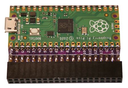
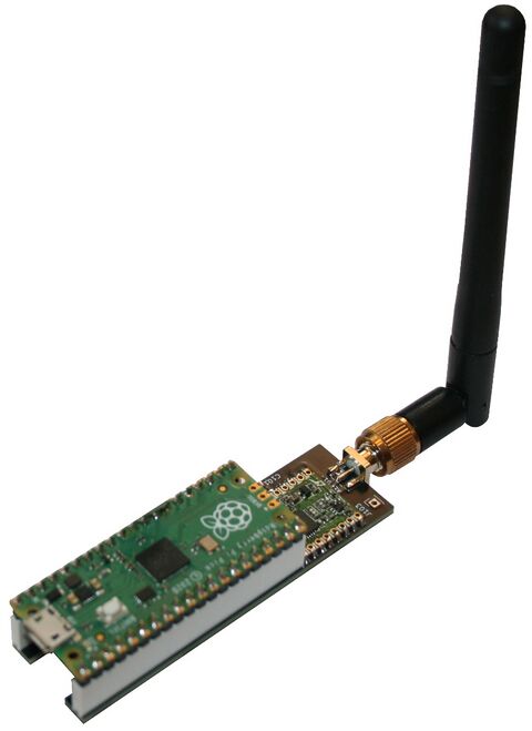
Within the CANSAT-KIT the Rapsberry-Pico is ready to use and can be plugged onto an PICO Radio board.

Connects the demonstration Antenna and you are ready to test.

ENG-CANSAT-V2-ASSEMBLY-21.jpg xxx
ENG-CANSAT-V2-ASSEMBLY-22.jpg xxxx
ENG-CANSAT-V2-ASSEMBLY-23.jpg xxx

Written by Meurisse D. for MCHobby

MCHobby investit du temps et de l'argent dans la réalisation de traduction et/ou documentation. C'est un travail long et fastidieux réalisé dans l'esprit Open-Source... donc gratuit et librement accessible.
SI vous aimez nos traductions et documentations ALORS aidez nous à en produire plus en achetant vos produits chez MCHobby.