Hack-ENG-MotorSkin-Assembler
Here a list of steps to assemble the motor-skin. All those steps should take in between 30 to 40 minutes.
Warm your iron we will start.
| Click on the images to display them in larger size. This helps to see important details |
| We recommend to check the component list before assembling the motor-skin. |
Part one
Les connecteurs
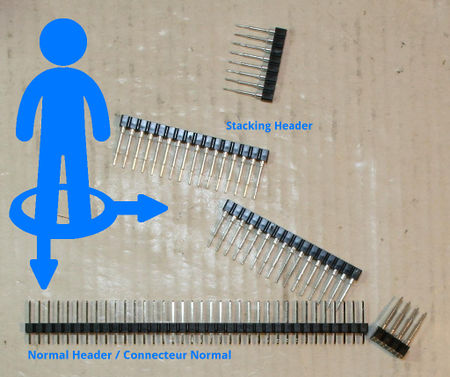
The motor-skin board is provided with a pinHeader section. You can also use a stacking header for PyBoard.
The stacking header would allows to stack board over the motor skin (or wiring your own components) to contrôle them with your pyboard.
We will show how to assemble the two types of connectors on the Motor-Skin
|
It is now time to choose the connector type:
You can select the connector included within the kit OR buy a set of stacking header for PyBoard. | ||
|
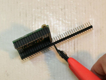
Using the standard pinHeader:
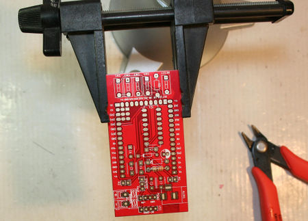
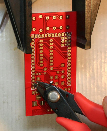
Place the section of pinHeader in the PyBoard connector and cut them to the appropriate length. | ||
|
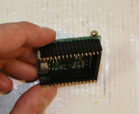
Repeat the operation to conver the 3 sides of the PyBoard.
You should have 2 sections of 16 pins + 1 section of 10 pins. | ||
|
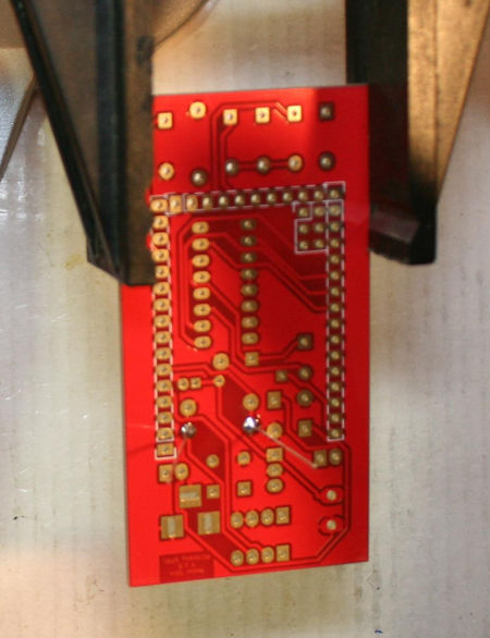
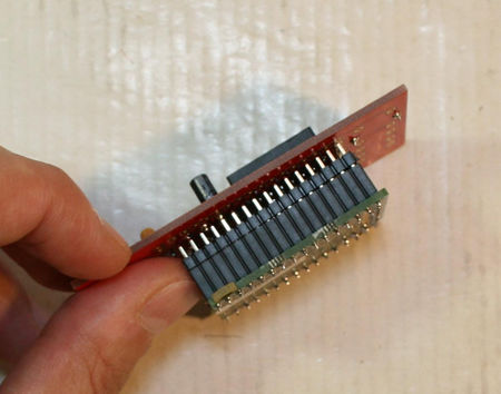
Place the motor-skin board over the pin-header.
The pinHeader's head should be visible through the holes of the Motor-Skin board. | ||
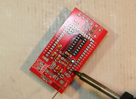
|
It is now time to use the iron to soler each of the pins on the motor-skin | ||
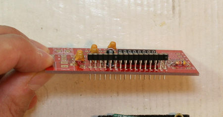
|
Using the stacking header:
Place all the sections of the kit "stacking header" on the motor-skin board. The plastic part of the connector should not go down to the board. They should stays a bit "higher" (as on the picture). | ||
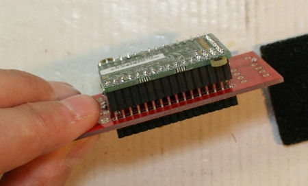
|
Then, it is very important to insert the motor-skin+connector on the PyBoard. This will align all the connectors properly before you starts the soldering phase. | ||
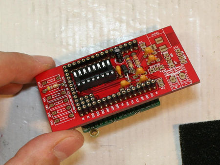
|
This picture shows the place for all the connectors. | ||
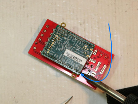
|
Now, upside-down the assembly and lay it down on you desk. Then fix some pins with a bit of stain (this operation will just fix the pinHeader on the motor-skin in the correct position... this should not be perfect by now).
This would help to keep the "perfect alignment" for further soldering phase.
| ||
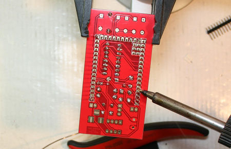
|
One the connector maintained with some soldering:
| ||
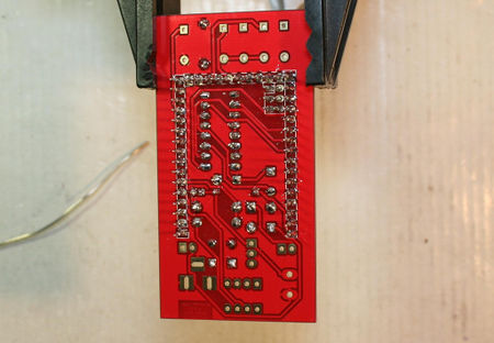
|
Voila, it is finish.
|
Second part
Now, we can finish our assembly operations.
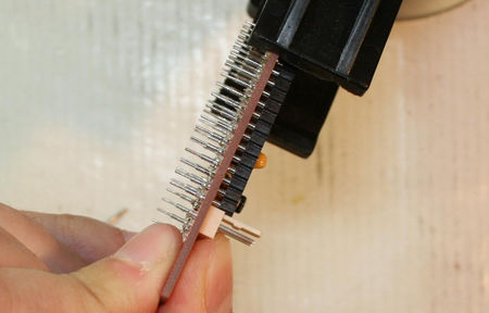
|
Place the connectors for M1 and M2.
Place them flat on the pinHeader (or stacking header) we just place on the board. Tips & tricks: to ease the soldering operation, you can place a tip of stain on the iron... then fix the connector with the stain. After you solder the second pinHeader properly. Finally you come back to the initial pin to finish up the soldering of the first pin. | ||
|
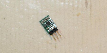
If you buy the Motor-skin Kit then it is the time to solder the S7V7F5 Pololu regulator- 5V step-up/step-down.
Solder the right angle connector on the pololu board (like shown on the picture). Once soldered, the pin should largely exceed from the regulator board. Take your diagonal cutter and shorten the pins flat to the board. | ||
|
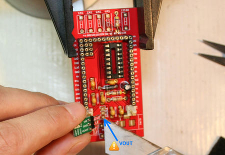
Place the pololu board on the motor-skin... the regulator's VOUT pin should be place on the Motor-skin's VOUT hole. | ||
|
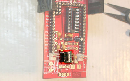
Solder the Pololu board on the motor skin as shown on this picture. | ||
|
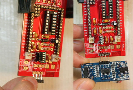
Place and solder the 1x4 connector on the board. This connector will thake the Ultrasonic HC-SR04 sensor in. | ||
|
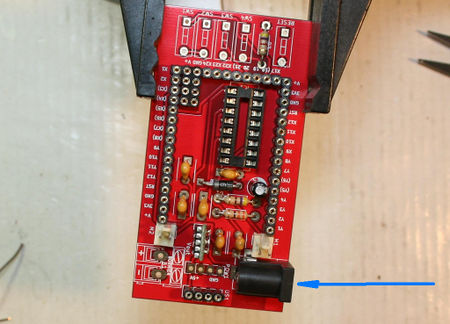
This the moment for placing the Power Jack connector.
With it, you can power your pyboard and the motors and the drivers of the Motor-Skin board from a batteries (10V Max!!!) The Jack connector uses the following power convention (the most common one):
| ||
|
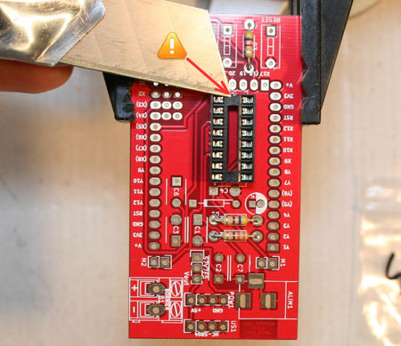
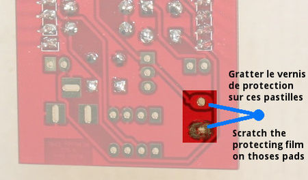
Before soldering the Jack, you will have to upside-down the board and remove a bit of the silkscreen. We accidently place a protection over one of the connector (like showed on the picture). | ||
|
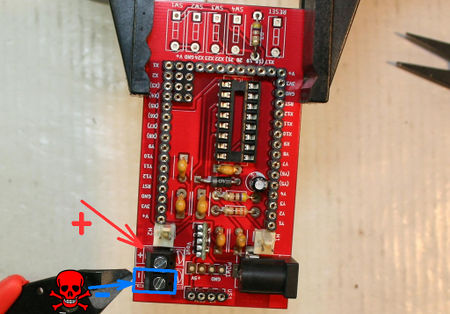
Then solder the other power terminal.
As the barrel jack connector, this terminal can be used to power the PyBoard and the motors + motor skin board from external batteries (10V Max!!!)
| ||
|
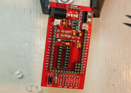
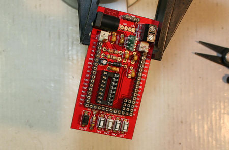
Solder the small black button on the place named Reset.
You can see this button on the top left position of the image. | ||
|
Then solder the 4 small white button on the places named SW1, SW2, SW3, SW4 | ||
|
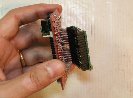
If you had selected the stacking headers on your Motor-Skin board then push it on your PyBoard.
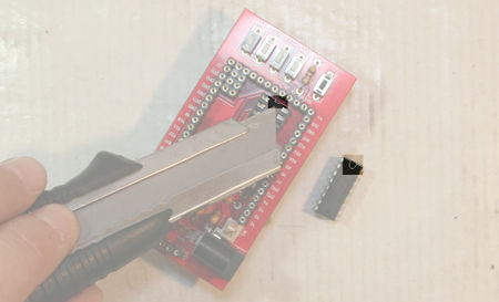
We will place the L293D on the IC holder. By doing so, we will not bend the stacking header pin if we are pushing to hard on the the L293D. | ||
|
Before we place the L293D chip, please note the half moon symbol on the chip which indicates the way to place the chip on the chip holder. | ||
|
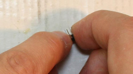
Place the side of the l293D on a place surface (on your desk).
Then apply a pressure to bend the pins (all in the same time, all in the same way). Do the same on the other side of the L293D chip. Repeat the operation several time on each side of the chip until it perfectly fit on the chip holder. | ||
|
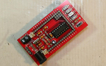
Voila! Your Motor-Skin board is ready. | ||
|
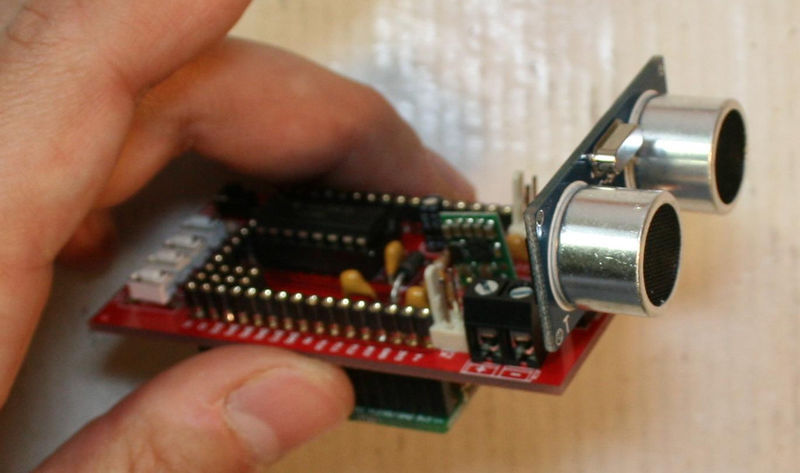
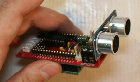
If you did buy a motor-skin Kit then you also have a HC-SR04 ultrasonic sensor that you can place on the Motor-Skin board. |
Créé par Meurisse D. pour MCHobby.be - Created by Meurisse D. for MCHobby.be
Every reference, text extract of this document should be accompagned with the following credit text : « produced/translated by MCHobby (www.MCHobby.be) - shop for kit and componants » together with a link to the source (so this page). The credit text must be applied on every type of media.
The commercial usage of this text/translation/project's content may be subject to royality fee. In every use case, you must also have the agreement of the initial owner (concerns translation work and content reuse)
