Hack-ENG-MotorSkin-Assembler
|
|
En cours de traduction/élaboration. |
Here a list of steps to assemble the motor-skin. All those steps should take in between 30 to 40 minutes.
Warm your iron we will start.
| Click on the images to display them in larger size. This helps to see important details |
| We recommend to check the component list before assembling the motor-skin. |
Part one
Les connecteurs
|
|
En cours de traduction/élaboration. |
The motor-skin board is provided with a pinHeader section. You can also use a stacking header for PyBoard.
The stacking header would allows to stack board over the motor skin (or wiring your own components) to contrôle them with your pyboard.
We will show how to assemble the two types of connectors on the Motor-Skin
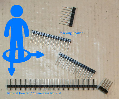
|
It is now time to choose the connector type:
You can select the connector included within the kit OR buy a set of stacking header for PyBoard. | ||
|
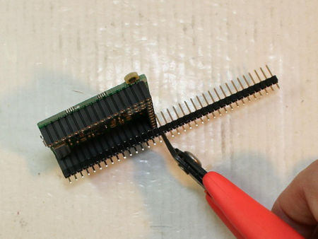
Using the standard pinHeader:
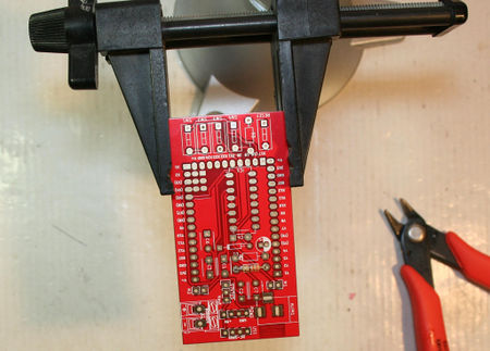
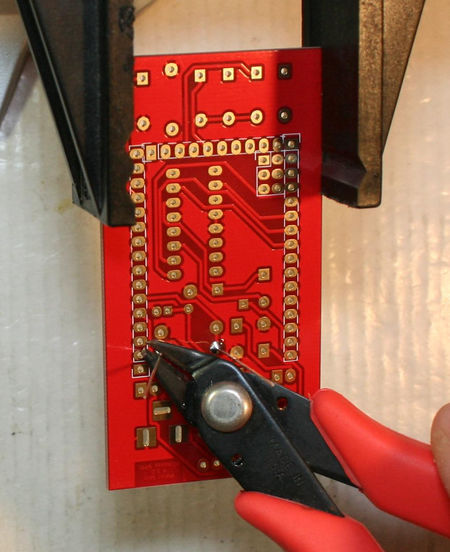
Place the section of pinHeader in the PyBoard connector and cut them to the appropriate length. | ||
|
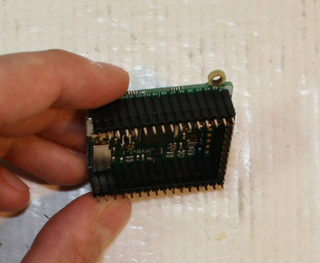
Repeat the operation to conver the 3 sides of the PyBoard.
You should have 2 sections of 16 pins + 1 section of 10 pins. | ||
|
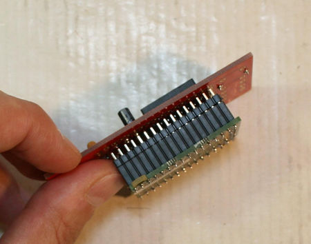
Place the motor-skin board over the pin-header.
The pinHeader's head should be visible through the holes of the Motor-Skin board. | ||
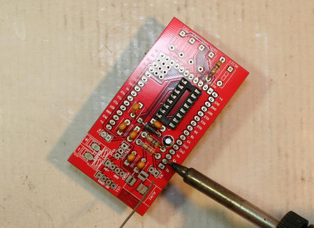
|
It is now time to use the iron to soler each of the pins on the motor-skin | ||
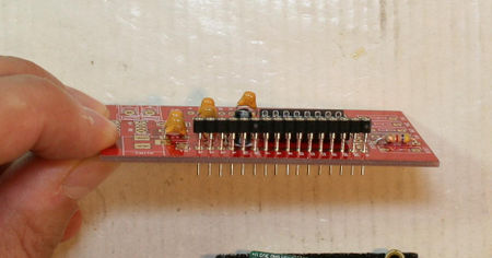
|
Using the stacking header:
Place all the sections of the kit "stacking header" on the motor-skin board. The plastic part of the connector should not go down to the board. They should stays a bit "higher" (as on the picture). | ||
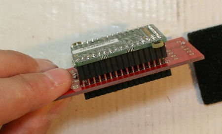
|
Then, it is very important to insert the motor-skin+connector on the PyBoard. This will align all the connectors properly before you starts the soldering phase. | ||
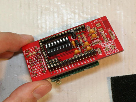
|
This picture shows the place for all the connectors. | ||
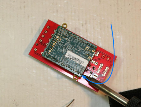
|
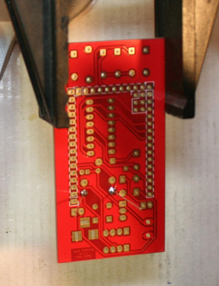
Now, upside-down the assembly and lay it down on you desk. Then fix some pins with a bit of stain (this operation will just fix the pinHeader on the motor-skin in the correct position... this should not be perfect by now).
This would help to keep the "perfect alignment" for further soldering phase.
| ||
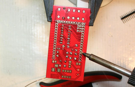
|
Une fois les connecteurs maintenu en place à l'aide de quelques soudures:
| ||
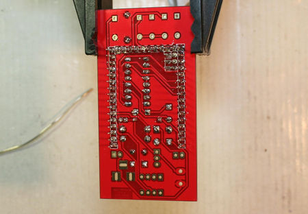
|
Voila c'est soudé.
Ces broches ne sont pas utilisés par le motor-skin, il n'est donc pas important qu'elles soient toutes soudées sur la carte. |
Deuxième partie
Nous pouvons maintenant poursuivre les opérations d'assemblage.
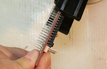
|
Placer les connecteurs des moteurs sur M1 et M2.
Placez les biens contre le connecteurs que nous venons de souder. Truc & astuce: pour souder ces connecteurs plus facilement, vous pouvez charger la panne de votre fer à souder avec de l'éteint... puis déposer une goûte d'étain sur une des broches du connecteur. Soudez ensuite l'autre broche du connecteur et rectifiez la soudure sur la première broche du connecteur. | ||
|
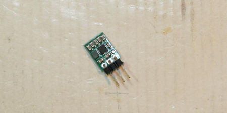
Si vous avez optez pour le Motor-skin Kit alors vous disposez d'un régulateur de tension Pololu S7V7F5 - 5V step-up/step-down.
Soudez le connecteur (à angle droit) sur le régulateur de tension. Comme indiqué sur l'image. Une fois soudé, les broches du connecteur dépasse beaucoup derrière le régulateur. Raccourcissez les à l'aide de votre pince coupante. | ||
|
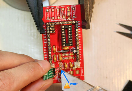
Faites correspondre la sortie VOut du régulateur à la pastille VOut sur la carte Motor-Skin. | ||
|
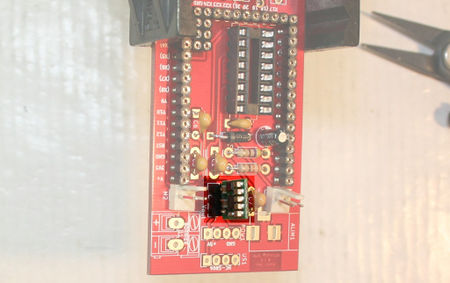
Une fois soudé, le régulateur est placé comme ci-contre sur la carte. | ||
|
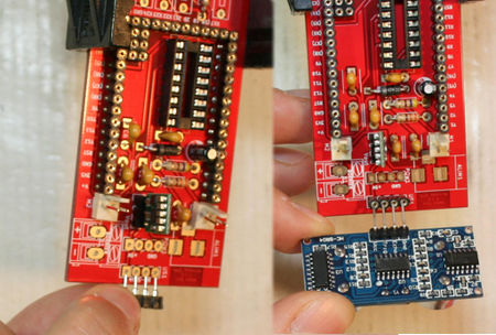
Placer et souder le connecteur 1x4 broche sur la carte. Ce connecteur permettra ensuite de placer le senseur Ultrason HC-SR04. | ||
|
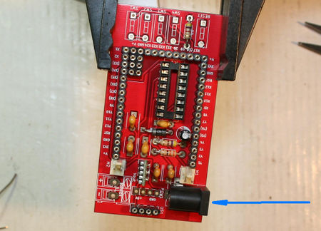
C'est le moment de placer le connecteur d'alimentation Jack.
Il permet d'alimenter votre Pyboard et l'étage moteur de la carte Motor-Skin à partir d'un bloc pile (10V Max!!!) Le connecteur jack utilise la polarité suivante:
| ||
|
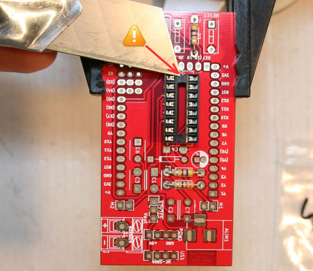
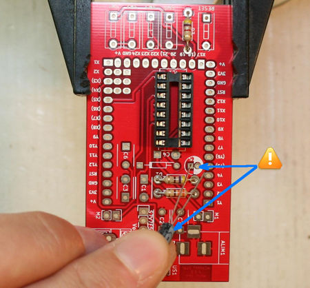
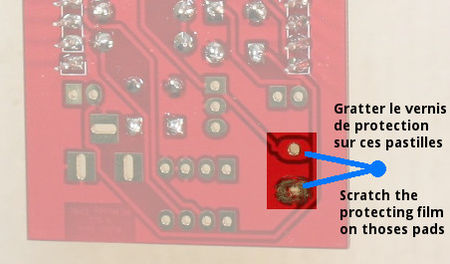
Avant de souder le bornier, il faut retourner la carte et enlever le verni de protection sur les pastilles en grattant à l'aide d'un cutter. | ||
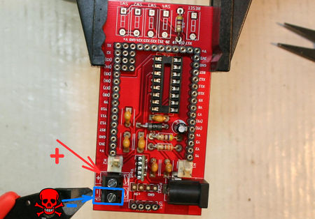
|
Souder ensuite l'autre bornier d'alimentation.
Tout comme le connecteur Jack, il permet d'alimenter votre Pyboard et l'étage moteur de la carte Motor-Skin à partir d'un bloc pile (10V Max!!!)
| ||
|
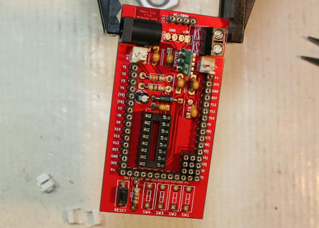
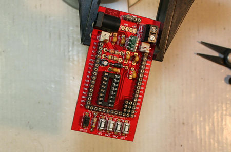
Souder le petit bouton noir sur l'emplacement marqué Reset.
Ce bouton est visible en bas à gauche de l'image | ||
|
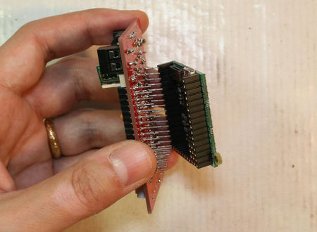
Souder ensuite le les quatres petits boutons blancs sur les emplacements SW1, SW2, SW3, SW4 | ||
|
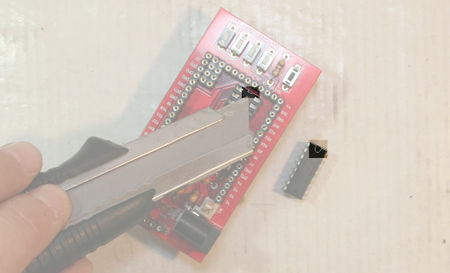
Si vous avez soudez des stacking headers sur votre Motor-Skin alors replacez le motor-skin sur votre PyBoard.
Nous allons placer le L293D sur le support, il serait dommage de tordre des broches en poussant trop fort sur le L293D. | ||
|
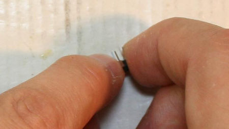
Avant d'insérer le L293D, revenons quelques secondes sur les détrompteurs qui indique comment orienter le L290D sur le support DIP 16. | ||
|
Placez une rangée de patte du L293D sur une surface plane (le bureau par exemple).
Puis appliquer une légère pression pour redresser les pattes. Faites pareil avec les pattes de l'autre côté du L293D. Répéter l'opération autant de fois que nécessaire jusqu'à ce que vous puissiez insérer les pattes du L293D sur le support. | ||
|
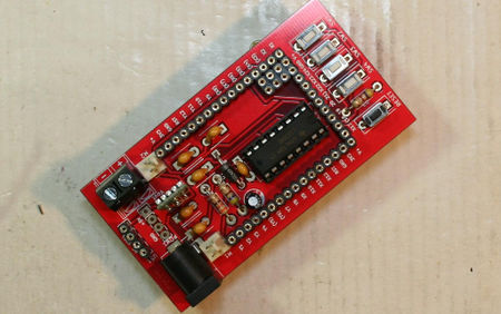
Voila, c'est terminé, votre carte Motor-Skin est prête. | ||
|
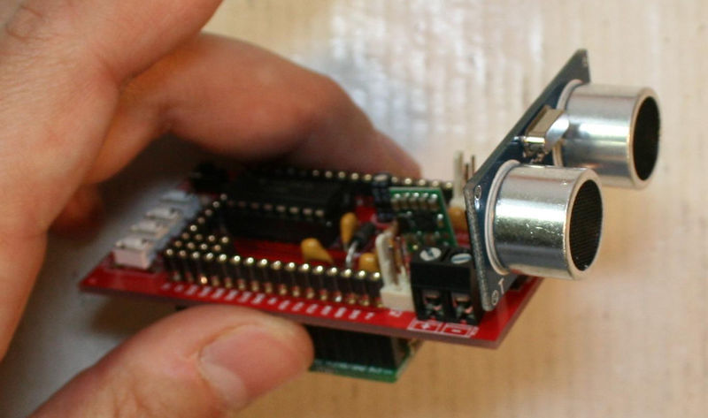
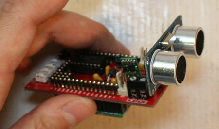
Si vous disposez du motor-skin Kit, vous disposez également d'un senseur Ultrason HC-SR04 que vous pouvez placer sur votre carte Motor-Skin. |
Créé par Meurisse D. pour MCHobby.be - Created by Meurisse D. for MCHobby.be
Every reference, text extract of this document should be accompagned with the following credit text : « produced/translated by MCHobby (www.MCHobby.be) - shop for kit and componants » together with a link to the source (so this page). The credit text must be applied on every type of media.
The commercial usage of this text/translation/project's content may be subject to royality fee. In every use case, you must also have the agreement of the initial owner (concerns translation work and content reuse)
