Pololu-Romi-32U4-Carte-Interface
|
|
En cours de traduction/élaboration. |
LEDs
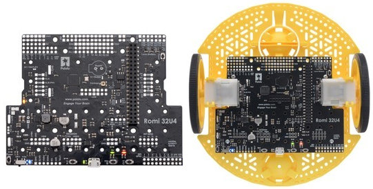
La carte de contrôle Romi 32U4 dispose de 5 LEDs indicatrices.
- Une LEDs jaune qui est connectée sur la broche digital 13 d'Arduino, ou PC7. Vous pouvez placer cette broche au niveau dans le programme utilisateur pour alumer la LED. Le bootloader 32U4 de l'A-Star fait pulser cette LED pendant qu'il attend le chargement d'un nouveau croquis.
- Une LED utilisateur verte est connectée sur la broche Arduino 30, ou PD5, et est allumée lorque la broche est placée au niveau bas. Lorsque la carte exécute le bootloader 32U4 de l'A-Star (ou un programme compilé dans l'environnement Arduino), cette LED flashera lorsqu'il y a des transmission de données via la connexion USB.
- Une LED utilisateur rouge est connectée sur la broche Arduino #17, ou PB0, et est allumée lorsque la pin est au niveau bas. Lorsque la carte exécure le bootloader 32U4 de l'A-Start (ou un programme compilé dans l'environnement Arduino), elle clignotera lorsque des données sont reçue via la connexion USB.
La bibliothèque Romi32U4 contient des fonction qui facilite le contrôle de des 3 LEDs utilisateurs. Les lignes de contrôle des LEDs utilisateurs sont également des lignes de données de l'écran LCD. Par conséquent, elle scintillent pendant la mise-à-jour du LCD. Les LED verte et rouge partagent également les lignes E/S des boutons poussoirs (voir plus bas).
- Une LED d'alimentation bleue à côté de l'interrupteur d'alimentation indique que le contrôleur reçoit une alimentation depuis les piles du Romi (Le circuit d'alimentation doit être sur la position marche).
- Une led d'alimentation verte près du connecteur USB (sur le bas de la carte) indique qu'une tension est présente sur le bus USB (VBUS).
Boutons poussoirs
The Romi 32U4 Control Board has five pushbuttons: a power button in the rear left corner, a reset button on the front right edge and three user pushbuttons located along the rear edge. The user pushbuttons, labeled A, B, and C, are on Arduino pin 14 (PB3), pin 30 (PD5), and pin 17 (PB0), respectively. Pressing one of these buttons pulls the associated I/O pin to ground through a resistor.
The three buttons’ I/O lines are also used for other purposes: pin 14 is MISO on the SPI interface, pin 30 and pin 17 control the green and red user LEDs, and all three pins are LCD data lines. Although these uses require the pins to be driven by the AVR (or SPI slave devices in the case of MISO), resistors in the button circuits ensure that the Romi 32U4 Control Board will not be damaged even if the corresponding buttons are pressed at the same time, nor will SPI or LCD communications be disrupted. The functions in the Romi32U4 library take care of configuring the pins, reading and debouncing the buttons, and restoring the pins to their original states.
Afficheur LCD
The Romi 32U4 Control Board has a set of through-holes in the center where a 2×7 header can be soldered to connect an 8×2 character LCD lien pololu (or any other LCD with the common HD44780 parallel interface (109k pdf)). You can adjust the LCD contrast with the potentiometer on the top right of the LCD connector. We recommend using a 2 mm slotted screwdriver to adjust the contrast.
The Romi32U4 library provides functions to display data on a connected LCD. It is designed to gracefully handle alternate use of the LCD data lines by only changing pin states when needed for an LCD command, after which it will restore them to their previous states. This allows the LCD data lines to be used for other functions (such as pushbutton inputs and LED drivers).
Note that the control board is not designed to allow both an LCD and a Raspberry Pi to plug into it at the same time. However, having an LCD header soldered to the board should not interfere with mounting a Raspberry Pi.
Buzzer
The buzzer lien pololu included with the Romi 32U4 Control Board can be soldered into the designated through-holes and used to generate simple sounds and music. By default, it is connected to digital pin 6 (which also serves as OC4D, a hardware PWM output from the AVR’s 10-bit Timer4). If you alternate between driving the buzzer pin high and low at a given frequency, the buzzer will produce sound at that frequency. You can play notes and music with the buzzer using functions in the Romi32U4 library. If you want to use pin 6 for an alternate purpose, you can disconnect the buzzer circuit by cutting the surface-mount jumper next to the buzzer.
Basé sur "Guide utilisateur de la carte de contrôle Romi 32U4" de Pololu (https://www.pololu.com/docs/0J69) - Traduit en Français par shop.mchobby.be CC-BY-SA pour la traduction
Toute copie doit contenir ce crédit, lien vers cette page et la section "crédit de traduction". Traduit avec l'autorisation expresse de Pololu (www.pololu.com)
Based on "Pololu Romi 32U4 Control Board User’s Guide" from Pololu (https://www.pololu.com/docs/0J69) - Translated to French by shop.mchobby.be CC-BY-SA for the translation
Copies must includes this credit, link to this page and the section "crédit de traduction" (translation credit). Translated with the Pololu's authorization (www.pololu.com)
