Spark-Photon-Tour
|
|
En cours de traduction/élaboration. |
{{ [[Text | Link | attributes] }}
Introduction
The Photon is a Wi-Fi development kit for internet-connected hardware. It is, in essence, the "brains" of a connected hardware product or project.
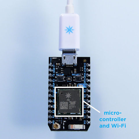
The Photon has on board a microcontroller, which is a small, low-cost, low-power computer that can run a single application. The microcontroller runs the show; it runs your software and tells the rest of the Photon what to do. It has a Real-Time Operating System (RTOS); it runs multiple threads at the same time, system tasks and user application tasks, switching between then depending on which task needs more system resources at that particular moment. The user tasks are coded in an application (often called firmware or an embedded application), which can be simple, just a few lines of code, or very complex, depending on what you want to do.
Le microcontroleur et WiFi

Crédit: Particle.IO www.particle.io
Microcontrollers are particularly good at controlling things; hence the name. They have a set of "pins" (the named connections along the edges of the board) that are called GPIO (General Purpose Input and Output) pins, or I/O pins. They can be hooked to sensors or buttons to listen to the world, or they can be hooked to lights and motors to act upon the world. These microcontroller's pins have been directly connected to the headers on the sides of the Core so you can easily access them; specifically, the pins labeled D0 to D7 and A0 to A7 are hooked directly to the microcontroller's GPIO pins.
The microcontroller can also communicate with other chips using common protocols like Serial (also called UART), SPI, CAN, or I2C (also called Wire). You can then make the Photon more powerful by connecting it to special-purpose chips like motor drivers or shift registers. Sometimes we'll wrap up these chips on a Shield, an accessory to the Photon that makes it easy to extend the capabilities of the Photon.
The Photon also has a Wi-Fi module, which connects it to your local Wi-Fi network in the same way that your computer or smartphone might connect to a Wi-Fi network. The Photon is programmed to stay connected to the internet by default, so long as it can find and connect to a network. Please note that your Wi-Fi module is a bit shy and does not like to be touched or compressed. This means that if you poke and prod the Wi-Fi module on your Photon, your device may reset.
When the Photon connects to the internet, it establishes a connection to Particle's Cloud. By connecting to the Cloud, the Photon becomes accessible from anywhere through a simple REST API. This API is designed to make it very easy to interface with the Photon through a web app or mobile app in a secure, private way, so that only you and those you trust can access the Photon.
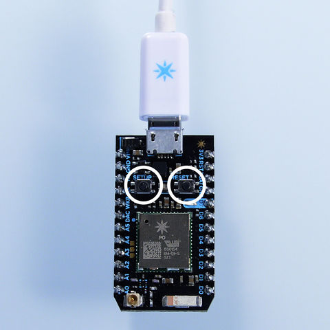
Les boutons

Crédit: Particle.IO www.particle.io
There are two buttons on the Photon:
- the RESET button (when holding the Photon with its USB-port to the top, it's the button on the right)
- the SETUP button (on the left).
The RESET button will put the Photon in a hard reset, effectively rebooting the microcontroller. This is a good way to restart the application that you've downloaded onto the Photon.
The SETUP button serves two functions after the Photon has booted:
- Hold down the SETUP button for three seconds to put the Photon into Soft-AP mode to connect it to your local Wi-Fi network. The LED should start flashing blue.
- Hold down the SETUP button for ten seconds to clear the Photon's memory of Wi-Fi networks.
The SETUP button serves four functions before the Photon has booted:
- Hold down the SETUP button, tap on the RESET button and wait for less than 3 seconds to enter User Safe Mode mode, where the RGB LED will be flashing Magenta. Release the SETUP button. This is the most frequently mode, because your user application will not execute. This can be useful if you have a bug in your code that is keeping you from re-flashing it over the air, or causing other hanging issues.
- Hold down the SETUP button, tap on the RESET button and wait for 3-6 seconds to enter Bootloader mode, where the RGB LED will be flashing Yellow. Release the SETUP button. In this mode you can reprogram the Photon over USB or JTAG. If you do this by accident, simply hit RESET button to leave Bootloader mode.
- Hold down the SETUP button, tap on the RESET button and wait for 6-10 seconds to enter Factory Reset Safe Mode mode, where the RGB LED will be flashing Green. Release the SETUP button. In this mode the Photon is reprogrammed with the software that was installed on the Photon in the factory (the Tinker application). The LED should turn white for three seconds and begin flashing quickly; when the LED switches to another color the Photon has been reset. This is useful if you encounter bugs with your firmware, or if you just want to get back to Tinker. Wi-Fi credentials are not erased in this mode.
- Hold down the SETUP button, tap once on the RESET button and wait for 10 seconds+ to do a Factory Reset, where the RGB LED will be flashing White. Release the SETUP button. In this mode the Photon is reprogrammed with the software that was installed on the Photon in the factory (the Tinker application). The LED should turn white for three seconds and begin flashing quickly; when the LED switches to another color the Photon has been reset. This is useful if you encounter bugs with your firmware, or if you just want to get back to Tinker. Wi-Fi credentials are also erased in this mode, so you'll have to set those up again.
Les LEDs
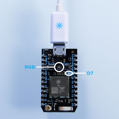
There are two LEDs on the Photon. The big fat one in the middle is a full-color RGB LED that shows you the status of the Photon's internet connection. The other small blue LED is the user LED; it's hooked up to D7, so when you turn the D7 pin HIGH or LOW, it turns on and off, respectively.

Crédit: Particle.IO www.particle.io
The RGB LED could show the following states:
| Couleur | Description |
| Flashing blue | Soft-AP setup mode, waiting for network information. |
| Solid blue | Soft-AP setup complete, network information found. |
| Flashing green | Connecting to local Wi-Fi network. |
| Flashing cyan | Connecting to Cloud. |
| High-speed flashing cyan | Cloud handshake. |
| Slow breathing cyan | Successfully connected to Cloud. |
| Flashing yellow | Bootloader mode, waiting for new code via USB or JTAG. |
| White pulse | Start-up, the Core was powered on or reset. |
| Flashing white | Factory Reset initiated. |
| Solid white | Factory Reset complete; rebooting. |
| Flashing magenta | Updating firmware, or entering Factory Reset Safe Mode. |
| Solid magenta | May have lost connection to the Cloud. Pressing the Reset (RST) button will attempt the update again. |
| The RGB LED can also let you know if there were errors in establishing an internet connection. A red LED means an error has occurred. |
These errors might include:
| Color | Description |
| Two red flashes | Connection failure due to bad internet connection. Check your network connection. |
| Three red flashes | The Cloud is inaccessible, but the internet connection is fine. Check our support page to make sure that all systems are operational. |
| Four red flashes | The Cloud was reached but the secure handshake failed. Visit our support page for help. |
| Flashing yellow/red | Bad credentials for the Cloud. Contact the Particle team at hello@particle.io |
Les broches
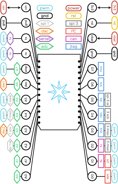
The Photon has 24 pins that you can connect a circuit to.

Crédit: Particle.IO www.particle.io
| Pin | Description |
| VIN | This pin can be used as an input or output. As an input, supply 3.6 to 5.5VDC to power the Photon. When the Photon is powered via the USB port, this pin will output a voltage of approximately 4.8VDC due to a reverse polarity protection series schottky diode between VUSB and VIN. When used as an output, the max load on VIN is 1A. |
| RST | Active-low reset input. On-board circuitry contains a 1k ohm pull-up resistor between RST and 3V3, and 0.1uF capacitor between RST and GND. |
| VBAT | Supply to the internal RTC, backup registers and SRAM (1.8 to 3.3VDC). |
| 3V3 | This pin is the output of the on-board regulator and is internally connected to the VDD of the WiFi module. When powering the Photon via VIN or the USB port, this pin will output a voltage of 3.3VDC. This pin can also be used to power the Photon directly (max input 3.3VDC). When used as an output, the max load on 3V3 is 100mA. NOTE: When powering the Photon via this pin, ensure power is disconnected from VIN and USB. |
| WKP | Active-high wakeup pin, wakes the module from sleep/standby modes. When not used as a WAKEUP, this pin can also be used as a digital GPIO, ADC input or PWM. |
| D0~D7 | Digital only GPIO pins. |
| A0~A9 | 12-bit Analog-to-Digital (A/D) inputs (0-4095), and also digital GPIOs. A6 and A7 are code convenience mappings, which means pins are not actually labeled as such but you may use code like analogRead(A7). A6 maps to the DAC pin and A7 maps to the WKP pin. |
| DAC | 12-bit Digital-to-Analog (D/A) output (0-4095), and also a digital GPIO. DAC is used as DAC1 in software, and A5 is a second DAC output used as DAC2 in software. |
| RX | Primarily used as UART RX, but can also be used as a digital GPIO or PWM. |
| TX | Primarily used as UART TX, but can also be used as a digital GPIO or PWM. |
Les broches PWM
When you want to use the analogWrite() function on the Photon, for instance to smoothly dim the brightness of LEDs, you need to use pins that have a timer peripheral. People often call these PWM pins, since what they do is called Pulse Width Modulation. The Photon has 9 PWM pins: D0, D1, D2, D3, A4, A5, A7, RX and TX.
Note:
The PWM timer peripheral is duplicated on two pins (A5/D2) and (A4/D3) for 7 total independent PWM outputs. For example: PWM may be used on A5 while D2 is used as a GPIO, or D2 as a PWM while A5 is used as an analog input. However A5 and D2 cannot be used as independently controlled PWM outputs at the same time.
Plus d'information
Envie de plus d'information? Voyez la fiche technique du Photon
Source: Particle Photon Hardware créé par Particle.IO.
Traduction réalisée par Meurisse D pour MCHobby.be - Translated by Meurisse D. for MCHobby.be
Traduit avec l'autorisation de Particle.IO - Translated with the permission from Particle.IO - Particle.IO
Toute référence, mention ou extrait de cette traduction doit être explicitement accompagné du texte suivant : « Traduction par MCHobby (www.MCHobby.be) - Vente de kit et composants » avec un lien vers la source (donc cette page) et ce quelque soit le média utilisé.
L'utilisation commercial de la traduction (texte) et/ou réalisation, même partielle, pourrait être soumis à redevance. Dans tous les cas de figures, vous devez également obtenir l'accord du(des) détenteur initial des droits. Celui de MC Hobby s'arrêtant au travail de traduction proprement dit.