Spark.IO-Démarrer
|
|
En cours de traduction/élaboration. |
Démarrer le Core
Le contenu de la boite
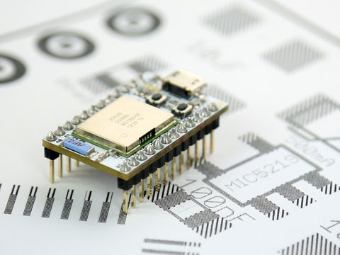
Félicitations, vous êtes l'heureux propriétaire d'un nouveau Spark Core!
Crédit: Particle.IO www.particle.io
Allons y, ouvrons la boîte et parlons un peu de ce qu'il y a dedans. Votre boite devrait contenir:
- Spark Core - La raison même de votre achat!
- Breadboard - Un breadboard pour facilement brancher des composants sur le Core dans devoir réaliser des soudures.
- USB cable - Inclus un câble USB, très pratique pour alimenter le Spark Core... nous couvrirons les aspects techniques plus tard.
Alimenter le core
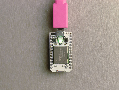
Branchez le cable USB sur votre Spark Core et ensuite sur votre Ordinateur. Le Core doit commencer à clignoter en bleu.
Vous avez un Spark Core avec connecteur µFL? N'oubliez pas de brancher votre antenne maintenant (avant la mise sous tension)!
Crédit: Particle.IO www.particle.io
Il ne clignote pas en bleu?
Peut être est-il déjà configuré. Maintenez le bouton MODE enfoncé jusqu'a ce qu'il commence à glignoter en bleu... ensuite, vous pouvez continuer.
Installer l'application
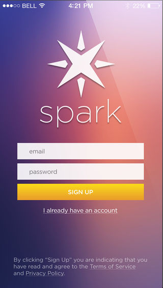
Vous pouvez chercher après l'application mobile s’appelant "Spark Core", vous pouvez également cliquer sur un des liens ci-dessous:
Crédit: Particle.IO www.particle.io
Entrez maintenant une adresse e-mail puis un mot de passe de votre choix (dans le champs "password").
Cliquez ensuite sur le bouton "Sign Up" pour créer un compte Spark!
Ce compte Spark sera nécessaire pour contrôler vos Spark Core connectés sur Internet.
Connectez votre Core sur le Cloud
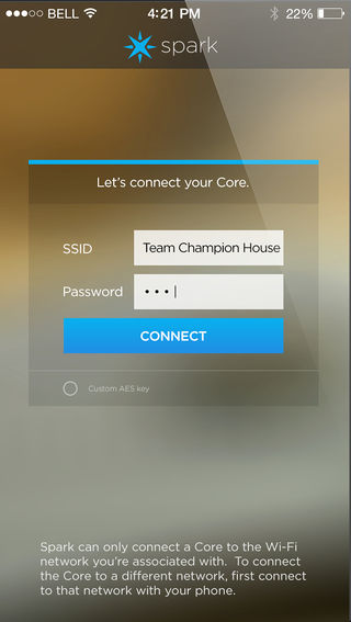
Assurez-vous que votre mobile soit bien connecté sur le réseau WiFi que vous voulez utiliser (le réseau WiFi s'affiche dans le zone SSID de l'app). Entrez ensuite votre mot de passe WiFi et cliquer sur CONNECT!
Cela pourrait prendre un peu de temps... alors ne vous inquiétez pas. La LEDs devrait prendre l'une des couleurs suivantes:
- Clignote en bleu: Recherche des informations d'identification WiFi (Listening for Wi-Fi credentials)
- Fixe en bleu: Obtention des info WiFi depuis l'application (Getting Wi-Fi info from app)
- Clignote en vert: Connexion sur le réseau WiFi.
- Clignote en Cyan: Connexion sur le Spark Cloud.
- Clignote en magenta: Mise-à-jour du Firmware à une version plus récente.
- Pulsation lente en cyan: Connecté!
Crédit: Particle.IO www.particle.io
Votre téléphone n'a pas trouvé de Cores?
Il ne clignote pas en bleu?
Faites un autre essais.
Il glignote en vert et ne devient pas cyan?
Réessayez encore en pressant le bouton MODE sur le Core jusqu'au moment où la LED clignote en bleu, vérifiez ensuite le nom et le mot de passe de votre réseau.
Il pulse en cyan mais mais il ne trouve pas de Core?
Votre Core est sur le réseau, mais cela à prit trop de temps. Nous allons devoir déclarer votre Core manuellement (claim your core manually).
Tout à fait autre chose?
Voyez également la page concernant "la connexion de votre Core" et n'hésitez pas à faire une recherche dans la communauté (Spark, Anglais).
Réaliser des choses
Faire clignoter une LED avec Tinker
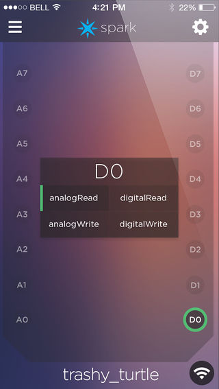
L'application Spark devrait maintenant afficher l'écran Tinker, comme celui présenté ci-dessous.
Cet écran s'appelle "DO" qui en anglais signifie "faire".
Cet écran propose plusieurs options:
- analogRead - pour lecture analogique
- analogWrite - pour écriture analogique (sortie PWM)
- digitalRead - pour lecture digital
- digitalWrite - pour écriture digital
Crédit: Particle.IO www.particle.io
Tappez sur D7 et ensuite sur digitalWrite dans la boite de dialogue qui s'affiche. Maintenant, lorsue vous tapez sur le cercle D7, une petite LED bleue devrait s'allumer ou s'éteindre! C'est parce que la LED partage une connexion avec la broche libellée D7 sur le Core.
Vous pourriez raccorder votre propre LED sur une autre broche du Core et faire de même pour l'allumer et l'éteindre.
En utilisant digitalRead vous pouvez savoir si un bouton est pressé. analogRead permet de connaître la position d'un potentiomètre.
Vous pouvez toujours réactiver Tinker sur votre core en suivant ces instructions.
Placer un programme sur votre Core
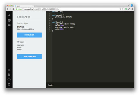
Maintenant, contrôlons la LED bleue en utilisant du code plutôt que Tinker. Si vous cliquez ici, vous atterrirez sur la page principale du l'IDE Spark nommé Build (environnement de développement Spark où vous pouvez ecrire votre code et le téléverser sur votre Core. Connectez vous sur "Build" avec la même adresse e-mail et le mot de passe utilisé lorsque vous avez ouvert votre compte Spark dans l'application mobile!
Crédit: Particle.IO www.particle.io
Click "BLINK AN LED" under the Example apps title. This code turns D7 (labeled led2) on and off, once a second. Click the lightning bolt icon in the upper left and it will upload or "flash" this code onto your Core. You'll see a series of status colors on the main LED, and then the little blue LED blinking. Magic!
You can find more info in the Web IDE (Build) page.
Présentation des éléments
The Spark Core is a Wi-Fi development kit for internet-connected hardware. It is, in essence, the "brains" of a connected hardware product or project.
The Core has on board a microcontroller, which is a small, low-cost, low-power computer that can run a single application. The microcontroller runs the show; it runs your software and tells the rest of the Core what to do. It doesn't have an Operating System the way that your computer does; it just runs a single application (often called firmware or an embedded application), which can be simple, just a few lines of code, or very complex, depending on what you want to do.
Microcontrollers are particularly good at controlling things; hence the name. They have a set of "pins" (little spider leg type things sticking off the chip) that are called GPIO (General Purpose Input and Output) pins, or I/O pins. They can be hooked to sensors or buttons to listen to the world, or they can be hooked to lights and motors to act upon the world. These microcontroller's pins have been directly connected to the headers on the sides of the Core so you can easily access them; specifically, the pins labeled D0 to D7 and A0 to A7 are hooked directly to the microcontroller's GPIO pins.
The microcontroller can also communicate with other chips using common protocols like Serial (also called UART), SPI, or I2C (also called Wire). You can then make the Core more powerful by connecting it to special-purpose chips like motor drivers or shift registers. Sometimes we'll wrap up these chips on a Shield, an accessory to the Core that makes it easy to extend the Core.
The Core also has a Wi-Fi module, which connects it to your local Wi-Fi network in the same way that your computer or smartphone might connect to a Wi-Fi network. The Core is programmed to stay connected to the internet by default, so long as it can find and connect to a network.
When the Core connects to the internet, it establishes a connection to the Spark Cloud. By connecting to the Cloud, the Core becomes accessible from anywhere through a simple REST API. This API is designed to make it very easy to interface with the Core through a web app or mobile app in a secure, private way, so that only you and those you trust can access the Core.
les boutons
There are two buttons on the Core: the RESET button (when holding the Core with its USB-port to the top, it's the button on the right) and the MODE button (on the left).
The RESET button will put the Core in a hard reset, effectively depowering and repowering the microcontroller. This is a good way to restart the application that you've downloaded onto the Core.
- Hold down the MODE button for three seconds to put the Core into Smart Config mode to connect it to your local Wi-Fi network. The LED should start flashing blue.
- Hold down the MODE button for ten seconds to clear the Core's memory of Wi-Fi networks.
- Hold down the MODE button, tap on the RESET button and wait for three seconds to enter Bootloader mode, where you can reprogram the Core over USB or JTAG. Release the MODE button when you see the LED flashing yellow. If you do this by accident, simply hit RESET button to leave Bootloader mode.
- Hold down the MODE button, tap once on the RESET button and wait for ten seconds to do a Factory Reset, where the Core is reprogrammed with the software that was installed on the Core in the factory (the Tinker application). The LED should turn white for three seconds and begin flashing quickly; when the LED switches to another color the Core has been reset. This is useful if you encounter bugs with your firmware, or if you just want to get back to Tinker.
LEDs
There are two LEDs on the Core. The big fat one in the middle is a full-color RGB LED that shows you the status of the Core's internet connection. The other small blue LED is the user LED; it's hooked up to D7, so when you turn the D7 pin HIGH ou <coe>LOW (respectivement: Niveau logique HAUT et BAS), it turns on and off, respectively.
The RGB LED could show the following states:
- Flashing blue: Listening mode, waiting for network information.
- Solid blue: Smart Config complete, network information found.
- Flashing green: Connecting to local Wi-Fi network.
- Flashing cyan: Connecting to Spark Cloud.
- High-speed flashing cyan: Spark Cloud handshake.
- Slow breathing cyan: Successfully connected to Spark Cloud.
- Flashing yellow: Bootloader mode, waiting for new code via USB or JTAG.
- White pulse: Start-up, the Core was powered on or reset.
- Flashing white: Factory Reset initiated.
- Solid white: Factory Reset complete; rebooting.
- Flashing magenta: Updating firmware.
- Solid magenta: May have lost connection to the Spark Cloud. Pressing the Reset (RST) button will attempt the update again.
he RGB LED can also let you know if there were errors in establishing an internet connection. Une LED rouge siginifie qu'une erreur est survenue. These errors might include:
- Two red flashes: Connection failure due to bad internet connection. Check your network connection.
- Three red flashes: The Cloud is inaccessible, but the internet connection is fine. Check our Twitter feed to see if there have been any reported outages; if not, visit our support page for help.
- Four red flashes: The Cloud was reached but the secure handshake failed. Visit our support page for help.
- Flashing yellow/red: Bad credentials for the Spark Cloud. Contact the Spark team (hello@spark.io).
Broches
The Core has 24 pins that you can connect a circuit to. These pins are:
- VIN: To power the Core off an unregulated power source with a voltage between 3.6V and 6V, or, if you're powering the Core over USB, this pin can be used as 5V V~OUT~ to power external components. In this case consider the current limitation imposed by your USB power source (e.g. max. 500mA for standard USB 2.0 ports). Avoid powering the Core via USB and V~IN~ concurrently.
- 3V3: This pin will output a regulated 3.3V power rail that can be used to power any components outside the Core. (Also, if you have your own 3.3V regulated power source, you can plug it in here to power the Core).
- 3V3*: This is a separate low-noise regulated 3.3V power rail designed for analog circuitry that may be susceptible to noise from the digital components. If you're using any sensitive analog sensors, power them from 3V3* instead of from 3V3.
- !RST: You can reset the Core (same as pressing the RESET button) by connecting this pin to GND.
- GND: These pins are your ground pins.
- D0 à D7: These are the bread and butter of the Spark Core: 8 GPIO (General Purpose Input/Output) pins. They're labeled "D" because they are "Digital" pins, meaning they can't read the values of analog sensors. Some of these pins have additional peripherals (SPI, JTAG, etc.) available, keep reading to find out more.
- A0 à A7: These pins are 8 more GPIO pins, to bring the total count up to 16. These pins are just like D0 to D7, but they are "Analog" pins, which means they can read the values of analog sensors (technically speaking they have an ADC peripheral). As with the Digital pins, some of these pins have additional peripherals available.
- TX et RX: These pins are for communicating over Serial/UART. TX represents the transmitting pin, and RX represents the receiving pin.
Broches PWM
When you want to use the analogWrite() function on the Core, for instance to smoothly dim the brightness of LEDs, you need to use pins that have a timer peripheral. People often call these PWM pins, since what they do is called Pulse Width Modulation. The Core has 8 PWM pins: A0, A1, A4, A5, A6, A7, D0 and D1.
Source: Particle Core Hardware créé par Particle.IO.
Traduction réalisée par Meurisse D pour MCHobby.be - Translated by Meurisse D. for MCHobby.be
Traduit avec l'autorisation de Spark.IO - Translated with the permission from Particle.IO - Particle.IO
Toute référence, mention ou extrait de cette traduction doit être explicitement accompagné du texte suivant : « Traduction par MCHobby (www.MCHobby.be) - Vente de kit et composants » avec un lien vers la source (donc cette page) et ce quelque soit le média utilisé.
L'utilisation commercial de la traduction (texte) et/ou réalisation, même partielle, pourrait être soumis à redevance. Dans tous les cas de figures, vous devez également obtenir l'accord du(des) détenteur initial des droits. Celui de MC Hobby s'arrêtant au travail de traduction proprement dit.