Différences entre versions de « ENG-CANSAT-PICO-USER-GUIDE »
(→UARTs) |
|||
| Ligne 163 : | Ligne 163 : | ||
| − | * '''RUN''' - | + | * '''RUN''' - This pin acts like '''Reset''' pin. Tie it to the ground and the the Pico immediately stops. |
| − | * '''3V3_EN''' - | + | * '''3V3_EN''' - Deactivate the 3.3V power regulator when tied to the ground. This will completely switch off the Pico power |
* '''GP23''' - PowerSave internal board pin. Depending on the conditions, this pin can reduce the power consumption of the board. | * '''GP23''' - PowerSave internal board pin. Depending on the conditions, this pin can reduce the power consumption of the board. | ||
| − | * '''GP24''' - | + | * '''GP24''' - This internal board pin is pulled HIGH when the board is connected to a computer or wall adapter (when VBus = 5V). |
| − | * '''GP25''' - | + | * '''GP25''' - Controls the onboard LED. The GP25 is not wired to a board pin. |
=== Debug Pins === | === Debug Pins === | ||
Version du 20 février 2022 à 23:34
Raspberry-Pi PICO
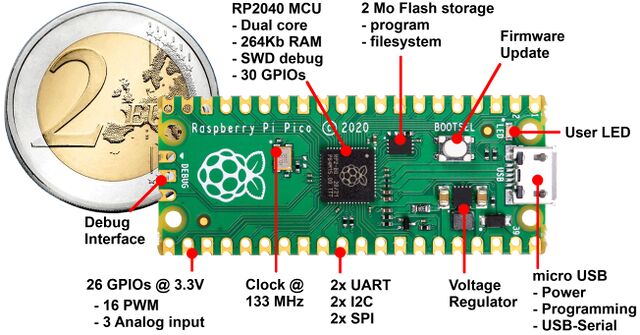
The Raspberry-Pi PICO use a RP2040 Dual Core ARM Cortex M0+ processor with 3.3V logic and 133 MHz. This chip embed 2 Mo of FLASH (64x more than the Atmega328/Uno) and has 264K RAM (132x more than UNO)!
| Pico Features |
| 26 GPIOs |
| 3 User Analog inputs 12 bits 2 others inputs are tied to VSYS/3, internal temp. sensor. |
| PWM on 16 pins |
| Hardware I2C (2) and SPI (2) buses |
| UART (1 User, 1 REPL) |
| SD IO, VGA IO |
| 8 PIO (programmable IO) |
| Feather are: |
| * Small (5.1x2.1 cm) |
| * Light (3.0Gr) |
| * Powerful |
| * Versatile |
| * bus relocation |
| * MicroPython Ready |
| * C++/Arduino compatible |
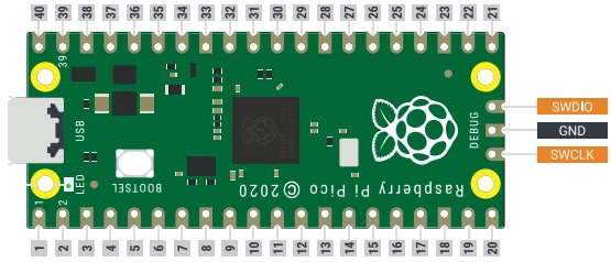
This Pico and the RP2040 have built-in USB 1.1 PHY (host and device support) which offers USB-to-Serial and debug feature (so no need for FTDI-like chip). The Pico also feature and 3 pins SWD debug port (mostly used for C development debugging with OpenOCD).
The Pico has the following specs:
- Size: 51mm x 23mm x 3.8mm
- Weight: 3 grams
- RP2040 @ 133MHz
- 3.3V logic/power
- 2048KB of FLASH
- 264KB of RAM
- 128KB MicroPython filesystem
- No EEPROM
- RTC & Clock based on 32.768 KHz crystal
- 3.3V regulator (300mA peak current) with Power/enable pin
- USB native support (has USB bootloader)
- 26 GPIO pins (16 PWM)
- Hardware Serial + Hardware I2C + Hardware SPI support
- 3 x 12-bit analog inputs (from 0 to 4095)
- No DAC analog ouput
- Interface for Lipo Charger
- Green LED attached on pin #25
- Reset pins (without button)
- FileSystem with file handling capabilities.
About the MicroPython file-system :
The Flash memory available on the Raspberry-Pi Pico do have several usages:
- It store the the MicroPython firmware including the ported Python libraries.
- It store the MicroPython File-System used for:
- Storing the user scripts (and datas)
- Allowing user script to manipulate files (data-logging)
- Storing addition library (user's defined library)
About the UF2 bootloader:
The Raspberry-Pi Pico is pre-loaded with an UF2 bootloader in the RP2040 microcontroler ROM. U2F mode makes the board looking like a USB Flash Drive when attached to a computer. It allows to upload a new firmware into the Flash.
| The MicroPython firmware is already uploaded while manufacturing the Pico board. So, in fine, there is no need to activates UF2 mode anymore. MicroPython does allows to store python scripts into the board via operation over the serial port (no need for UF2 mode in this case). |
Pressing the "boot" button while powering up the Pico will activates the UF2 mode. Simply drag an UF2 firmware on the USB Flash drive to completely reprogram the firmware running on the board (No special tools, No special drivers needed)! The UF2 bootloader can be used to load up a newer version of MicroPython, Arduino IDE compiled firmware, C++ firmware, CircuitPython (derivative version of MicroPython made from Adafruit Industries), etc.
Pico pinout
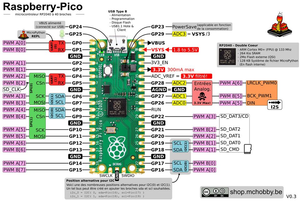
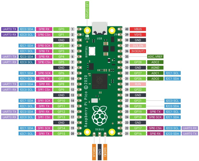
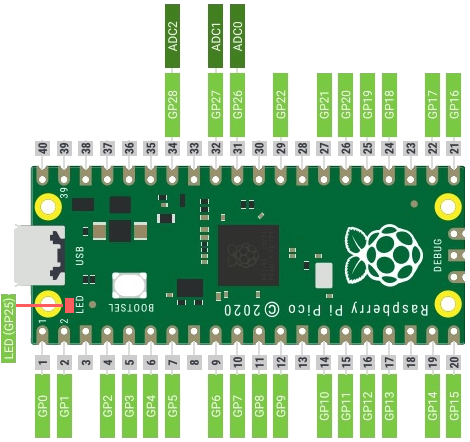
The Pinout here below is an enhanced documented version of the official PinOut.
On the following pinout, only the default position of each bus is annoted.
The official pinout contains the same bus at several positions. This may looks confusing but possible thanks to the "Bus Fabric" feature of the RP2040.
To benefits from the "Bus Fabric", the pin used must be mentionned when creating the bus instance (the simplified pinout demonstrated this for the I2C bus #0 & #1).
| We strongly recommend to relies on the default bus location to not over-complicates code writing and schematics understanding. |
Pico pins description
Power Pins
- VBUS - Does have 5V when the Pico micro USB is plugged onto a computer (or PSU). Python code also detect VBUS by querying the GP24 pin (goes HIGH when 5V is present).
- VSYS - allows to power-up the Pico from an external power source from 1.8 to 5.5V (lipo battery). The voltage on this pin can be monitored with analog pin GP26 (=VSYS/3). It is quite useful to warn the user when the battery must be refill. GP26 is not exposed on the GPIO connector.
- 3V3 - Output of the 3.3V onboard regulator. That pin can deliver up to 300mA to your project. This step-up/step-down 3.3V regulator is powered from VSYS.
- 3V3_EN - Tied this pin to the ground to disable the 3.3V regulator and shutdown the Pico.
- GND - common ground.
Digital Pins
| Never exceed 3.3V, neither apply negative voltage, to any of the Pins |
Digital Pins can be used as:
- Input - allowing the python script to read the state of the Pin. The pin is driven by external component or sensor setting.
- the read state returns HIGH when the pin is set to 3.3V.
- the read state returns LOW when the pin is tied to the GND (0 Volt).
- Output - allowing the python script to write the state of the Pin. The pin can produce (or absorb) some current to drive an external component or sensor.
- WHEN set to HIGH by Python code THEN the microcontroler drives the pin to 3.3V.
- WHEN set to LOW by Python code THEN the microcontroler drives the pin to GND (0 Volt).
Please note:
- The analog input pins can also be used as digital input/output pins.
- The onboard LED is controlled by the pin GP25. The GP25 is not wired to a board pin.
Analog Pins
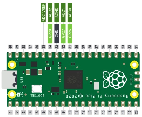
The Pico does expose 3 analog inputs pins. Each pin can read a voltage between 0 and 3.3V.
- GP28 - also known as ADC2 (analog input 2).
- GP27 - also known as ADC1 (analog input 1).
- GP26 - also known as ADC0 (analog input 0).
- GP26 - not exposed on the board pin, the voltage applied to GP26 equal VSYS/3. It can be used to monitor the external power source/battery voltage.
- AGND - Reference ground for analog reading.
- ADC_VREF - Analog input voltage reference. It is the 3.3V with additional filtering. Do not applies any voltage to this pin, do not use it to supply power to the project.
UARTs
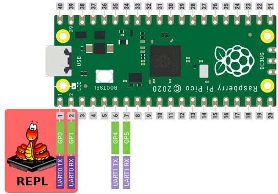
The Pico have many buses but one must be highlighted, it is UART(0). UART is often referred as serial port.
MicroPython does offers an interactive command line interpreter named REPL (Read, Evaluate, Print Loop).
REPL is available over:
- USB connector
- UART(0) : just plug a console cable to get access to the REPL via the UART(0) RX & TX.
REPL on UART(0)
Special Pins
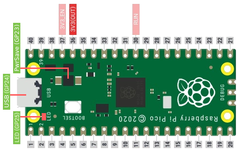
- RUN - This pin acts like Reset pin. Tie it to the ground and the the Pico immediately stops.
- 3V3_EN - Deactivate the 3.3V power regulator when tied to the ground. This will completely switch off the Pico power
- GP23 - PowerSave internal board pin. Depending on the conditions, this pin can reduce the power consumption of the board.
- GP24 - This internal board pin is pulled HIGH when the board is connected to a computer or wall adapter (when VBus = 5V).
- GP25 - Controls the onboard LED. The GP25 is not wired to a board pin.
Debug Pins
- SWCLK et SWDIO - those contact points, visible under the board, are used to program the microcontroler. You can also use thoses contact to connect the SWD debugger.
Pico Ressource
The Github of MCHobby contains useful PICO ressources for designing schematic and board with the Pico.
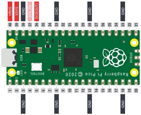
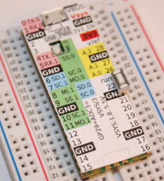
The Pico overlay help to identifies Pins on the Pico.
Written by Meurisse D. for MCHobby

