ENG-CANSAT-PICO-POWERING
Abstract
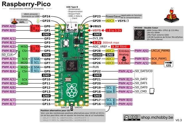
There are several way to power the power the Pico and your project.
The Pico run with 3.3V and can be powered with a voltage up to 5.5V. As the Pico voltage regulator is a Step-down/Step-up regulator (reduce/up-raise the source voltage) you can power it directly from batteries. Even when the battery voltage falls down under 3.3V the Pico will be able to run anyway.
Despite the simplicity to directly powering the Pico from a battery or a Lipo, there is also some interest to use specialized charging/discharging circuitery.
How to power the Pico
The Pico can be powered:
- Via the USB : so with 5V
- Via the VSYS pin : with battery having max 5.5V
- With a Battery management circuitery and smart wiring ;-) (as seen here below)
The Pico can be easily shutdown by placing the 3V3_EN pin to the ground.
This will deactivate the Pico 3.3V DC/DC regulator and spare the battery power.
Wiring a Lipo Booster on the Pico
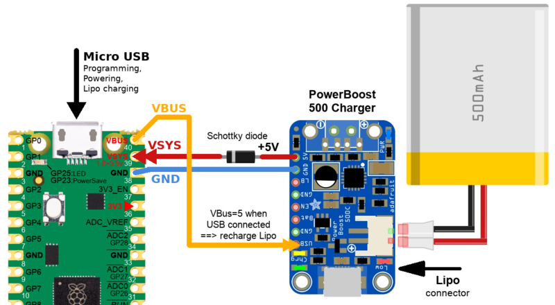
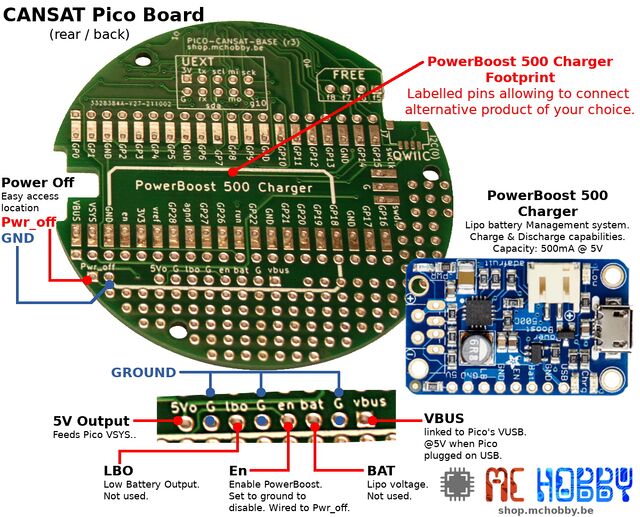
Pico and PowerBoost 500
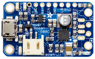
Crédit: AdaFruit Industries www.adafruit.com
| Do not confuse PowerBoost 500 charger with the PowerBoost 1000 charger which have a slightly different PinOut. |
The Adafruit PowerBoost 500 is a breakout board able:
- to discharge a Lipo battery to generates 5V output (500mA max)
- to charge the Lipo battery when connected to an external 5V supply
- to do the both operations at the same time.
The great thing about the PowerBoost is that microUSB connector is optional to charge the Lipo.
Just powering the breakout with 5V on the USB pin will have exactly the same effect than plug-in the USB cable.
Here how it works. Please note that only the Pico Micro USB is used in this setup.
When Pico is plugged on a computer:
For sure, you can program and interact with the board.
On the powering aspect:
- The Pico and its 3.3V regulator are powered via USB
- The Pico VBUS pin is set to 5V
- The Pico VSYS pin is also at 5V. Thanks to the diode, the 5V VSYS does not inject current into the 5V output of the PowerBoost charger.
- The 5V VBUS (on the Pico) do power the PowerBoost on the USB pin. As a result, the PowerBoost does charge up the Lipo.
Summary: the Pico is running and the Lipo is charging.
When Pico is UNPLUG from computer:
- The Pico VBUS is at 0V
- The Pico VSYS is at 0V (but this will change).
- The Pico regulator is not powered
- As the PowerBoost is running, it generates 5V on its 5V Output Pin. The 5V push the current through the diode to VSYS
- The Pico VSYS now receives 5V (a bit lower due to the diode lost). So the Pico regulator is powered and generating 3.3V.
Summary: the Pico is running and the Lipo is discharging.
How to power off:
To power-off the Pico when the USB is unplug on the Pico, we have the following options:
- Tied the Pico 3V3_EN pin to the ground : that disable the Pico but the Powerboost is still discharging and producing 5V.
- Tied the PowerBoost EN pin to the ground : this disable the PowerBoost which stops to power up the Pico. The best approach.
Pico and PowerBoost 1000
If you needs more Power to juice your project, a PowerBoost 1000 Charger can be used instead of a PowerBoost 500 Charger.
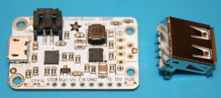
Crédit: AdaFruit Industries www.adafruit.com
The PowerBoost 1000 works the same way as the PowerBoost 500 but deliver an higher current and have a slightly different pinout, respect the pin name while wiring the Powerboost 1000 and it will work the same.
For Cansat Pico Kit, the "Assembling section" contains useful details to quickly solder it onto your board.
The Adafruit PowerBoost 1000 is a breakout board able:
- to discharge a Lipo battery to generates 5V output (1000mA / 1A max)
- to charge the Lipo battery when connected to an external 5V supply
- to do the both operations at the same time.
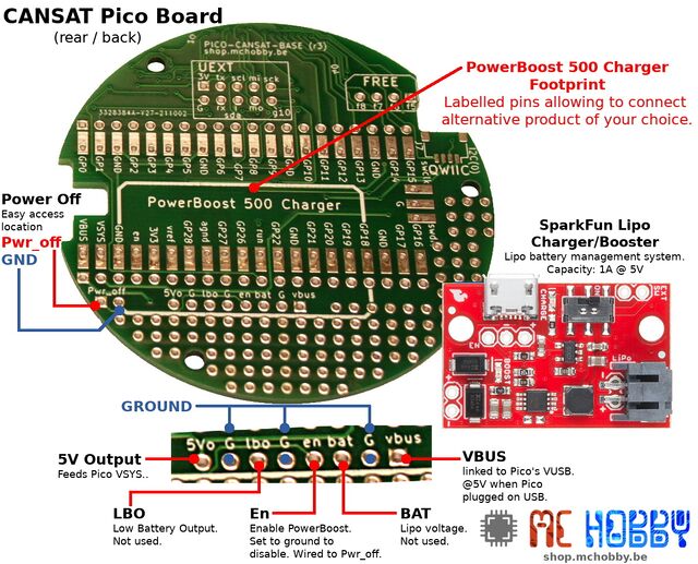
Pico and Sparkfun Lipo Charger/Booster
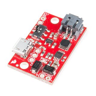
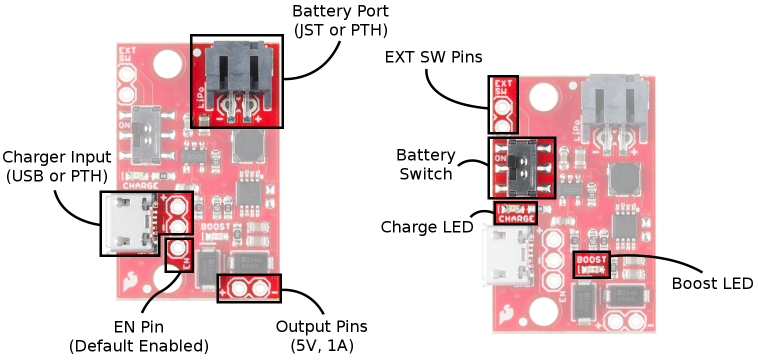
If you have a SparkFun 5V/1A Lipo charger/booster, this can also be used with this project.
The Sparkfun Lipo Charger/Booster is capable to deliver an higher current (up to 1 Amp) and have a different pinout from Adafruit's powerboost version.
For Cansat Pico Kit, the "Assembling section" contains useful details to quickly solder it onto your board.
The SparkFun 5V/1A Lipo charger/booster is a breakout board able:
- to discharge a Lipo battery to generates 5V output (1000mA / 1A max)
- to charge the Lipo battery when connected to an external 5V supply
- to load the Lipo battery while the project consume some power (20mA max to ensure sleep operation).
The great thing about the Booster/Charger is that microUSB connector is optional to charge the Lipo.
Just powering the breakout with 5V on the 5V USB will have exactly the same effect than plug-in the USB cable.
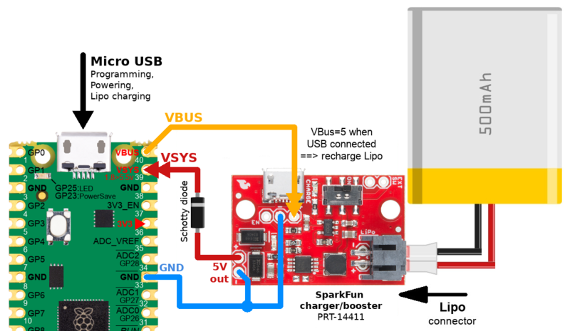
Here how it works. Please note that only the Pico Micro USB is used in this setup.
When Pico is plugged on a computer:
For sure, you can program and interact with the board.
On the powering aspect:
- The Pico and its 3.3V regulator are powered via USB
- The Pico VBUS pin is set to 5V
- The Pico VSYS pin is also at 5V. Thanks to the diode, the 5V VSYS does not inject current into the 5V output of the Sparkfun Lipo Charger/Booster.
- The 5V VBUS (on the Pico) do power the Sparkfun Lipo Charger/Booster on the USB pin. As a result, the Lipo Charger/Booster does charge up the Lipo.
Summary: the Pico is running (20 mA max) and the Lipo is charging.
When Pico is UNPLUG from computer:
- The Pico VBUS is at 0V
- The Pico VSYS is at 0V (but this will change).
- The Pico regulator is not powered
- As the SparkFun Lipo Charger/Booster is running, it generates 5V on its 5V Output Pin. The 5V push the current through the diode to VSYS
- The Pico VSYS now receives 5V (a bit lower due to the diode lost). So the Pico regulator is powered and generating 3.3V.
Summary: the Pico is running and the Lipo is discharging.
How to power off:
To power-off the Pico when the USB is unplug from the Pico, we have the following options:
- Tied the Pico 3V3_EN pin to the ground : that disable the Pico but the Lipo Charger/Booster is still discharging and producing 5V.
- Tied the Lipo Charger/Booster EN pin to the ground : this disable the the Power/Booster which stops to power up the Pico. The best approach.
Cansat Kit and Lipo Chargers
With Adafruit PowerBoost
The Kit Cansat with Pico does have a footprint to receive an Adafruit PowerBoost 500 charger. This works exactly as described above but with all the wiring already done on the board.
Just place the PowerBoost under the board (place it over the drawed footprint) and solder it with the help of a PinHeader.
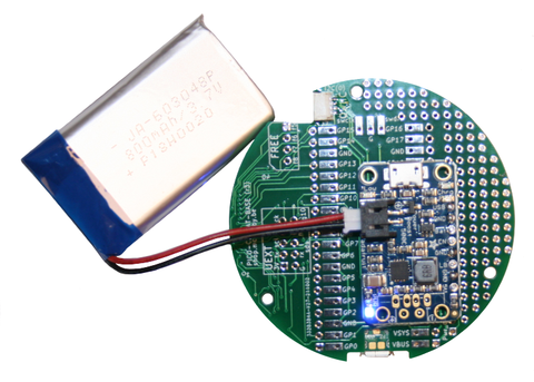
Once soldered, plug a LiPo battery and the final setup should look like the following:
| Some third-party LiPo cells have JST connectors wired opposite from the standard! Connecting these to the PowerBoost will damage your PowerBoost. Double check the polarity before connecting. |
What are the features:
- Plug the USB on the Pico to refill the LiPo.
- Unplug the USB to make the LiPo powering the CanSat.
- The PWR_OFF connector (near the border of the board) can be fitted with a switch. Close the switch (so PWR_OFF tied to the ground) to deactivates/shutdown the PowerBoost.
- PowerBoost status LEDs are visible under the CanSat (see next section for description).
- PowerBoost LBO pin (Low Battery Output) is accessible on the breakout and may be useful to report battery state over the radio.
| WARNING: Do not connect LBO pin directly to a 3.3V GPIO! |
About LBO pin: the LBO Pin is pulled high to BAT voltage (so 4.2V when battery is fully charged) in normal operation. When the battery voltage drops under 3.2VDC then the LBO pin is tied to the ground.
PowerBoost Status LEDs:
The PowerBoost is filled with several LEDs indicating useful status.
- Blue LED: next to the Powerboost USB A footprint, that LED indicates the 5V output status.
- Red LED: next to the JST connector, indicates the Low battery Voltage (LiPo voltage falls under 3.2VDC).
- Yellow LED: next to the PowerBoost micro USB, the Lipo battery is charging.
- Green LED: next to the PowerBoost micro USB, the Lipo battery is fully charged.
With SparkFun Lipo Charger/Booster
The Kit Cansat with Pico does have a footprint to receive an Adafruit PowerBoost 500 charger. This can also be used with a SparkFun Lipo Booster/Charger.
The Lipo charger must be wired to the Lipo Charger/Booster breakout as indicated in the assembly section the "Assembling section".
We do recommend to wire the Lipo Charger/booster UNDER the base plate (to preserve access to the Pico signals on the top).
Once soldered, plug a LiPo battery.
| Some third-party LiPo cells have JST connectors wired opposite from the standard! Connecting these to the PowerBoost will damage your PowerBoost. Double check the polarity before connecting. |
What are the features:
- Plug the USB on the Pico to refill the LiPo.
- Unplug the USB to make the LiPo powering the CanSat.
- The PWR_OFF connector (near the border of the board) can be fitted with a switch. Close the switch (so PWR_OFF tied to the ground) to deactivates/shutdown the Lipo Charger/Booster.
- The status LEDs are visible under the CanSat (see next section for description).
- The SparkFun Lipo charger/booster do no offer LBO pin (Low Battery Output).
Charger/Booster Status LEDs:
The onboard Blue LED indicates the charge status of the Lipo battery.
- No battery: LED floating (should be OFF but may flicker).
- Shutdown: LED floating (should be OFF but may flicker).
- Charging: LED ON.
- Fully Charged: LED off.
Additional ressources
- PowerBoost 500 charger tutorial (French)
- SparkFun Lipo Charger/Booster tutorial (English)
Written by Meurisse D. for MCHobby
