Différences entre versions de « ENG-CANSAT-ANTENNA »
(Contenu remplacé par « {{ENG-CANSAT-NAV}} {{COMMON-CANSAT-ANTENNA}} {{ENG-CANSAT-TRAILER}} ») Balise : Contenu remplacé |
|||
| (54 versions intermédiaires par le même utilisateur non affichées) | |||
| Ligne 1 : | Ligne 1 : | ||
{{ENG-CANSAT-NAV}} | {{ENG-CANSAT-NAV}} | ||
| − | + | {{COMMON-CANSAT-ANTENNA}} | |
| − | |||
| − | |||
| − | |||
| − | |||
| − | |||
| − | |||
| − | |||
| − | |||
| − | |||
| − | |||
| − | |||
| − | |||
| − | |||
| − | |||
| − | |||
| − | |||
| − | |||
| − | |||
| − | |||
| − | |||
| − | |||
| − | |||
| − | |||
| − | |||
| − | |||
| − | |||
| − | |||
| − | |||
| − | |||
| − | |||
| − | |||
| − | |||
| − | |||
| − | |||
| − | |||
| − | |||
| − | |||
| − | |||
| − | |||
| − | |||
| − | |||
| − | |||
| − | |||
| − | |||
| − | |||
| − | |||
| − | |||
| − | |||
| − | |||
| − | |||
| − | |||
| − | |||
| − | |||
| − | |||
| − | |||
| − | |||
| − | |||
| − | |||
| − | |||
| − | |||
| − | |||
| − | |||
| − | |||
| − | |||
| − | |||
| − | |||
| − | |||
| − | |||
| − | |||
{{ENG-CANSAT-TRAILER}} | {{ENG-CANSAT-TRAILER}} | ||
Version actuelle datée du 20 février 2022 à 00:40

Introduction
The RFM69HCW Testing shows how to transmit data back and forward between 2 radio modules.
This looks simple with the homemade quarter wave antenna, but better antenna design is required for long distance communication.
 |
What ever you do, the antenna is always the most sensitive component when working with radio communication.
Wrong antennas design may ruin the communication below 10 meter. Great antenna design with attention to details will allow the RFM69 module to transmit data quite over 4 Km (I tested it in second article and this former article). The antenna is the key to transmit data over a long distance! |
Before blaming a radio module think twice to the following:

- 23 watts covers 24 milliard of Km.
- 1 watt covers 1.04 milliard of Km.
- 0.1 watt covers 100 million of Km.
A RFM69 radio module at 20 dBm have an emitting power of 0.1 watt (100 mW).
Compared to Voyager I, the 100 mW of the RFM69 should be quite enough to transmit the data over kilometers.
Remark:
using a rule of three between the Voyager I distance and radio power is a bit over-simplistic but is good enough to demonstrate the possibility of sending data on long distance with RFM69 @ 433 MHz.
The "Antenna for Cansat" booklet
The following booklet is available under licence Creative Common BY-SA-NC-ND .
- BY-NC-ND : Author attribution required. Share-alike only, without modification, without commercial use.
- SA : Share alike licence (licence cannot be modified)
Please refer this booklet with a link to this page.

All those little things that will your antenna working a different way!
7 Rules for Radio Antennas

- Rule #1: Use short, high quality and thick antenna cables.
- Rule #2: An SWR below 2 is acceptable (less than 11% of power is reflected so we have much of the power available for transmission).
- Rule #3: Always connect an antenna to the sender (otherwise 100% of signal is reflected, which may kill the sender)
- Rule #4: Keep the polarization of your antennas the same way.
- Rule #5: The more dBi, the more power in one direction.
- Rule #6: With a proper antenna setup, the distance in air is not an issue if we have a line of sight.
- Rule #7: Longer is not always better for antennas. Smarter is better.
All coming from the famous video of Andreas Spiess.
Getting Help from Radio Amateur
Designing and testing an antenna for long distance communication is an intensive work.
You could find some help from our Radio Amateurs friends.
To locate a Radio Amateur Club near of your home then have a look the "Maker's Maps" owned at MC Hobby.
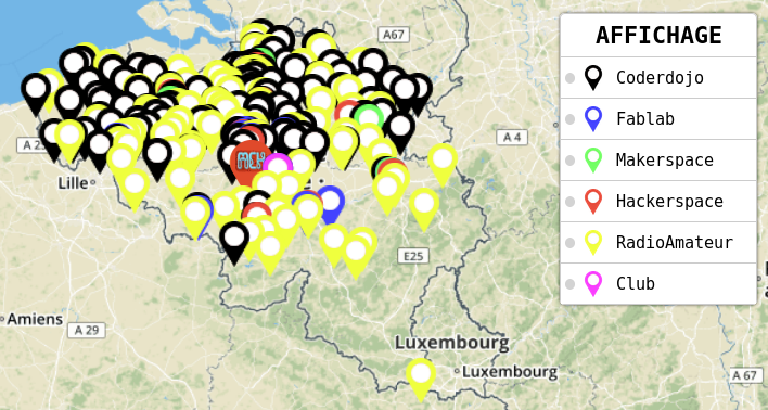
A yellow mark indicates the Radio Amateur clubs.
Written by Meurisse D. from MC Hobby - License: CC-SA-BY.