While reading [https://arduino103.blogspot.com/2018/08/ballons-meteorologiques-tout-savoir-sur.html some resources on the QSO magazine] (Magazine from Belgian Radio Amateur Association written in dutch and french), we did discover a Yagi Antenna tuned for 433Mhz.
−
−
[[Fichier:ENG-CANSAT-ANTENNA-10.png|640px]]<small><br />Source: QSO Magazine via [https://arduino103.blogspot.com/2018/08/ballons-meteorologiques-tout-savoir-sur.html this publication] - '''click to enlarge'''</small>
−
−
This antenna was engineered from the "[http://df.mchobby.be/ballon-meteo/cheapyagy.pdf Cheap Yagy]" (''pdf''), issue from the "[http://www.wa5vjb.com/yagi-pdf/cheapyagi.pdf Controlled Impedance 'Cheap' Antennas]" article written by Kent Britain WASVJB.
−
−
A simple rule of three can be used to adapt the antenna to other frequencies (the antenna was already adapted from a 432 Mhz design).
−
−
=== 6 or 11 elements ===
−
The Yagi antenna showed here upper does have 6 elements.
−
−
From a deeper read of the [https://arduino103.blogspot.com/2018/08/ballons-meteorologiques-tout-savoir-sur.html QSO magazines series], we learned that 6 elements Yagi can offer a gain up to 11.2 dBi.
−
−
It seems that the 11 elements Yagi ([http://df.mchobby.be/ballon-meteo/cheapyagy.pdf see original document]) '''will double the gain'''. Whoaw!!!
−
−
=== About Yagi Antenna ===
−
The antenna lengths and spacing are depending on the wavelength to capture.
−
−
[[Fichier:ENG-CANSAT-ANTENNA-30.png]]<small><br />Source: [https://www.elprocus.com/design-of-yagi-uda-antenna/ design of Yagi Uda Antenna]</small>
−
−
* '''Directors''' : used to drive the signal in the given direction. Those directors are usually shorter than driven element (about 5%).
−
* '''Driven element''' : is the element that capture or emit the signal.
−
* '''Reflector''' : reflect the signal toward (or coming from) the driven element. The reflector is larger than driven element (about 5%).
As specified by the CanSat settlement, everything should be contained within a defined volume (the Can).
−
−
So, the antenna should also fit into the volume.
−
−
However, '''once the can is released in the air, your project can deploy an antenna'''.
−
−
A well designed antenna for sending the data would also reduce the error ratio on the ground station.
−
−
== Getting Help for Antenna ==
−
Designing and testing an antenna for long distance communication is an intensive work.
−
−
You could find some help from our Radio Amateurs friends.
−
−
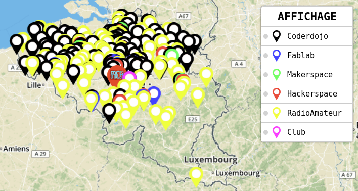
To locate a [http://map.mchobby.be Radio Amateur Club] near of your home then have a look [http://map.mchobby.be the "Maker's Maps"] owned at MC Hobby.
The antenna is the key to transmit data over a long distance!
Before blaming a radio module think twice to the following:
23 watts covers 24 milliard of Km.
1 watt covers 1.04 milliard of Km.
0.1 watt covers 100 million of Km.
A RFM69 radio module at 20 dBm have an emitting power of 0.1 watt (100 mW).
Compared to Voyager I, the 100 mW of the RFM69 should be quite enough to transmit the data over kilometers.
Remark: using a rule of three between the Voyager I distance and radio power is a bit over-simplistic but is good enough to demonstrate the possibility of sending data on long distance with RFM69 @ 433 MHz.
The "Antenna for Cansat" booklet
The following booklet is available under licence Creative Common BY-SA-NC-ND .
BY-NC-ND : Author attribution required. Share-alike only, without modification, without commercial use.
SA : Share alike licence (licence cannot be modified)
Please refer this booklet with a link to this page.