Différences entre versions de « ENG-CANSAT-PICO-HowTo »
| (59 versions intermédiaires par le même utilisateur non affichées) | |||
| Ligne 4 : | Ligne 4 : | ||
This section of the tutoriel contains small portion of code explaining how to use digital pins, analog pins, buses and all the fundamentals to control the board with Python code. | This section of the tutoriel contains small portion of code explaining how to use digital pins, analog pins, buses and all the fundamentals to control the board with Python code. | ||
| − | Everything you learned about | + | Everything you learned about Python 3 language like variables, loops, conditionals, object programming, ... does applies to MicroPython. |
A large part of standard Python libraries have been ported to MicroPython (partially or completely). Keep in mind that MicroControler doesn't have as much power and as much memory than a regular computer. So choice has been made: no gregorian calandar, no numpy (it exists some port anyway), no TKinter. | A large part of standard Python libraries have been ported to MicroPython (partially or completely). Keep in mind that MicroControler doesn't have as much power and as much memory than a regular computer. So choice has been made: no gregorian calandar, no numpy (it exists some port anyway), no TKinter. | ||
| + | |||
| + | === Needs some helps about python? === | ||
| + | |||
| + | [[Fichier:ENG-CANSAT-PICO-HowTo-Help-Me.png]] | ||
| + | |||
| + | This tutorial is not a training course about Python. Anyway, Python is quite easy to learn and do not requires lot of efforts. | ||
| + | |||
| + | Here follows some fundamentals help links about the Python language himself: | ||
| + | * [https://www.w3schools.com/python/ '''W3Schools''' on Python] : one of the best ressource for learning online (should I say "my favorite one). | ||
| + | * [https://www.pythoncheatsheet.org/#Python-Basics '''P'''ython'''C'''heat'''S'''heet.org] : Anyone can forget how to make loop, list, dictionary, tuple, list slice, math operator, generator... | ||
| + | * [https://www.pythonsheets.com/ pythonsheets.com] : more advanced cheat sheet. | ||
== Print and Waits == | == Print and Waits == | ||
| Ligne 12 : | Ligne 23 : | ||
Everything you will {{fname|print()}} will be sent to REPL (so over the USB-Serial line) and being visible in Thonny. | Everything you will {{fname|print()}} will be sent to REPL (so over the USB-Serial line) and being visible in Thonny. | ||
| + | |||
| + | This is incredibly useful to debug your software! | ||
<syntaxhighlight lang="python"> | <syntaxhighlight lang="python"> | ||
| Ligne 21 : | Ligne 34 : | ||
</syntaxhighlight> | </syntaxhighlight> | ||
| − | You can also sleep for milliseconds with {{fname|sleep_ms(x)}} | + | You can also sleep for milliseconds with {{fname|sleep_ms(x)}}. |
| + | |||
| + | [[Fichier:ENG-CANSAT-PICO-HowTo-print.png]] | ||
== Control an output == | == Control an output == | ||
| Ligne 99 : | Ligne 114 : | ||
That method returns a 16 bits value, so a number between 0 and 65535. | That method returns a 16 bits value, so a number between 0 and 65535. | ||
| − | {{ambox|text=Even if the {{fname|read_u16()}} returns a 16 bits values, the effective ADC resolution is still 12 bits. The MicroPython internal will just upscale the ADC value from 0..4095 to returned value 0..65535 by applying a multiplier.}} | + | {{ambox|text=Even if the {{fname|read_u16()}} returns a 16 bits values, the effective ADC resolution is still 12 bits. The MicroPython internal will just upscale the ADC value from 0..4095 to returned value 0..65535 by applying a multiplier. |
| + | |||
| + | The effective ADC reading precision is 3.3V/4095 = 0.000805V (0.8mv) }} | ||
[[Fichier:ENG-CANSAT-FEATHER-PICO-HowTo-25.png]] | [[Fichier:ENG-CANSAT-FEATHER-PICO-HowTo-25.png]] | ||
| Ligne 125 : | Ligne 142 : | ||
== PWM Output == | == PWM Output == | ||
| − | The | + | PWM stand for ''Pulse Width Modulation''. |
| + | |||
| + | PWM is a method for reducing the average power delivered by an electrical signal. The average voltage that feds the load is controlled by fastly switching on & off the power between supply and load. | ||
| + | |||
| + | {{ambox|text=PWM is abusively named "''Analog Output''" but don't be fooled by this expression, PWM is not a True analog output (like DAC is).}} | ||
| + | |||
| + | [[Fichier:ENG-CANSAT-FEATHER-PICO-pwm-01.png]] | ||
| − | + | The average voltage (average power) of PWM signal depend on the duty cycle: Vavg = 3.3V * Th / T | |
| + | |||
| + | [[Fichier:ENG-CANSAT-FEATHER-PICO-pwm-02.png|800px]] | ||
| + | |||
| + | Obviously, a 0% duty cyle is equivalent to a LOW signal whereas a 100% duty cycle is a HIGH signal. | ||
| + | |||
| + | In the following example, we will use PWM to dim the light on the onbloard LED. | ||
| + | |||
| + | The onboard LED is tied to the GPIO 25 (and PWM will work there as with other GPIOs). | ||
| + | |||
| + | Thank to PWM we can effectively control the LED luminosity (very low duty cycle will dim the light while highest duty cycle will make it brightest). | ||
<syntaxhighlight lang="python"> | <syntaxhighlight lang="python"> | ||
| − | from machine import Pin | + | from machine import Pin, PWM |
| − | + | pwm25 = PWM( Pin(25) ) | |
| − | + | pwm.duty_u16( 65534 ) # 100% | |
| − | + | pwm.duty_u16( 32767 ) # 50% | |
| − | + | pwm.duty_u16( 0 ) # 0% = LOW | |
</syntaxhighlight> | </syntaxhighlight> | ||
| + | |||
| + | {{underline|Notes:}} | ||
| + | * {{fname|PWM}} class must have a {{fname|Pin}} instance as argument. | ||
| + | * {{fname|duty_u16()}} must have an 16 bits integer value (0 to 65534) for the duty cycle. | ||
| + | * The effective '''Max duty_u16() value is 65534'''. A regression bug would make the 65535 (real max of 16 bits) equivalent to 0 !?!?!... this Phenix bug is coming back again and again. | ||
== Hardware buses == | == Hardware buses == | ||
=== I2C Bus === | === I2C Bus === | ||
| − | + | An I2C bus is a very popular serial bus in electronic to connect sensors and electronics to a microcontroler. Some DIY Maker companies did also use some "normalized" connectors around I2C bus. You may probably already ear words about [https://www.sparkfun.com/qwiic Qwiic from SparkFun], [https://learn.adafruit.com/introducing-adafruit-stemma-qt StemmaQt from Adafruit] (Qwiic compatible), [https://wiki.seeedstudio.com/Grove_System/ Grove from SeeedStudio]. | |
| + | |||
| + | Maybe not the fastest bus, this bus is easy to wire and to manage and requires only 2 wires: | ||
| + | * SDA: Serial Data | ||
| + | * SCL: Serial Clock | ||
| + | |||
| + | The I2C protocol use an address (0..127) to contact the target board with request and waiting for response. For sure each sensor boards must have an unique address on the I2C. On I2C implementation, the microcontroler do always keeps the control over the I2C communication. | ||
| + | |||
| + | [[Fichier:ENG-CANSAT-FEATHER-PICO-I2C.png|640px]] | ||
| + | |||
| + | The Pico do have several I2C bus as [[ENG-CANSAT-PICO-USER-GUIDE|mentionned on the PinOut diagram]], look for the blue boxes. | ||
| + | |||
| + | [[fichier:ENG-CANSAT-PICO-PINOUT.jpg|560px]] | ||
| + | |||
| + | {{ambox|text=We do highly recommend to use the I2C(0) bus as it is connected to kit Qwiic connector and UEXT connector.}} | ||
| + | |||
| + | [[Fichier:ENG-CANSAT-FEATHER-PICO-I2C-02.png|480px]] | ||
<syntaxhighlight lang="python"> | <syntaxhighlight lang="python"> | ||
| − | from machine import | + | from machine import I2C |
| − | + | ||
| − | + | i2c = I2C( 0 ) # sda=GP8, scl=GP9 @ 400 KHz (default) | |
| − | + | # i2c = I2C( 0, freq=100000 ) # Reduce bus speed @ 100 KHz | |
| − | |||
</syntaxhighlight> | </syntaxhighlight> | ||
| + | |||
| + | More information about I2C bus on the [https://docs.micropython.org/en/latest/library/machine.I2C.html official MicroPython I2C documentation]. | ||
| + | |||
| + | You may find lot of sensor driver: | ||
| + | * [https://github.com/mchobby/esp8266-upy Plateform Agnostic MicroPython Driver (esp8266-upy)] (''MCHobby, GitHub'') | ||
| + | * [https://forum.micropython.org/viewforum.php?f=15 Programs, Libraries and tools] (''MicroPython Forums'') | ||
| + | * [https://awesome-micropython.com/ Awesome MicroPython] (''awesome-micropython.com'') | ||
=== UART Bus === | === UART Bus === | ||
| − | The | + | The UART is often compared to a serial port (which is in facts very similar to). |
| + | |||
| + | It allows to send and receives data from a device using the same interface like modem, GPS, terminal. UART/Serial ports are used to creates point to point communication. | ||
| + | |||
| + | When wiring an UART, the RX & TX connection must be cross-over like the wiring to GPS here below (see the [https://github.com/mchobby/esp8266-upy/tree/master/gps-ultimate gps-ultimate MicroPython library]) | ||
| + | |||
| + | [[Fichier:ENG-CANSAT-PICO-HowTo-UART.png|480px]] | ||
| + | |||
| + | {{ambox|text=It is advised to use the UART(0) on GP0 & GP1. Indeed, UART(1) overlaps the SPI(0) used for Radio module. Alternative UART(1) position overlaps the I2C(0) bus. See the [[ENG-CANSAT-PICO-USER-GUIDE|Pinout]] for details.}} | ||
| + | |||
| + | <syntaxhighlight lang="python"> | ||
| + | from machine import UART, Pin | ||
| + | |||
| + | # UART(0) on GP0 & GP1 | ||
| + | uart = UART( 0, baudrate=9600) | ||
| + | |||
| + | # UART(1) on GP4 & GP5 | ||
| + | uart = UART( 1, baudrate=9600, timeout=3000) | ||
| + | |||
| + | # Alternate position for UART(1) by using Bus Fabric feature | ||
| + | uart = UART( 1, rx=Pin(9), tx=Pin(8), baudrate=9600 ) | ||
| + | </syntaxhighlight> | ||
| + | |||
| + | Outside of connecting device (like GPS) to the UART, you can also use an UART to get the REPL over it (exactly like USB connexion but over an UART. This may be kindly useful to bring a REPL connectivity over mobile network/device. | ||
| + | |||
| + | The following snip of code duplicates the REPL over the {{fname|UART(0)}} . | ||
<syntaxhighlight lang="python"> | <syntaxhighlight lang="python"> | ||
| − | from machine import | + | from machine import UART |
| − | + | from os import dupterm | |
| − | + | ||
| − | + | uart = UART(0, baudrate=19200, bits=8, parity=None, stop=1) | |
| − | + | os.dupterm( uart, 1 ) # Pico Firmware must be recompile with dupterm() | |
</syntaxhighlight> | </syntaxhighlight> | ||
| + | The {{fname|UART}} class is [https://docs.micropython.org/en/latest/library/machine.UART.html fully described into MicroPython documentation]. | ||
| + | |||
| + | The {{fname|dupterm()}} function is [https://docs.micropython.org/en/latest/library/os.html#terminal-redirection-and-duplication described here into the MicroPython documentation]. | ||
| + | |||
| + | {{underline|Tips & Tricks:}} | ||
| + | * One of the key parameter of UART is the {{fname|timeout}} parameter which indicates the timeout (in ms) to receive the end-of-line on {{fname|UART.readline()}} . | ||
| + | * See this [https://forums.raspberrypi.com/viewtopic.php?t=304410 Raspberry-Pi forum thread] to compile a dupterm() enabled firmware for Pico. | ||
=== SPI Bus === | === SPI Bus === | ||
| − | The | + | An SPI bus is high speed full duplex bus. |
| + | * High speed means several mega-hertz (can be up to +20 MHz). | ||
| + | * Full duplex means communicates in both direction at the same time. | ||
| + | |||
| + | Thanks to its high throughput, the SPI bus are used for display, data acquisition, data transmission, etc. | ||
| + | |||
| + | {{ambox|text=The Cansat RFM69 Radio module of Cansat kit do use {{fname|SPI(0)}} bus to exchange data with the MicroControler.}} | ||
| + | |||
| + | SPI bus are short (below 10cm) and uses '''3 wires for the data bus + a "Slave Select" wire per device''': | ||
| + | * MOSI: Master Out Slave In. Communication from the microcontroler to the device. | ||
| + | * MISO: Master In Slave Out. Communication from the device to the microcontroler. | ||
| + | * SCLK: Clock signal giving the rythme to the data transfer. | ||
| + | * SS: Slave Select (activated at LOW) used to activate the device on the bus. It is also used to start "transaction" with the device. | ||
| + | |||
| + | [[Fichier:ENG-CANSAT-PICO-HowTo-SPI.png]] | ||
| + | The following snip of code creates an instance of the {{fname|SPI(0)}} bus | ||
<syntaxhighlight lang="python"> | <syntaxhighlight lang="python"> | ||
| − | from machine import Pin | + | from machine import Pin, SPI |
| − | + | ||
| − | + | ss = Pin( 5, Pin.OUT, value=1 ) # Slave Select in deactivated state by default. | |
| − | + | # SPI(0) : GP4=Miso, GP5=/SS, GP6=Sck, GP7=Mosi | |
| − | + | # reducing clock speed to 400 KHz | |
| + | spi = SPI( 0, baudrate=400000 ) | ||
</syntaxhighlight> | </syntaxhighlight> | ||
| + | |||
| + | {{underline|Tips & Tricks:}}<br />Under MicroPython the SS pin is not "hardware" tied to a given SPI bus. User can freely choose any pin as "Slave Select" pin. | ||
== Additional tutorials == | == Additional tutorials == | ||
Version actuelle datée du 7 mars 2022 à 14:16
MicroPython How To
This section of the tutoriel contains small portion of code explaining how to use digital pins, analog pins, buses and all the fundamentals to control the board with Python code.
Everything you learned about Python 3 language like variables, loops, conditionals, object programming, ... does applies to MicroPython.
A large part of standard Python libraries have been ported to MicroPython (partially or completely). Keep in mind that MicroControler doesn't have as much power and as much memory than a regular computer. So choice has been made: no gregorian calandar, no numpy (it exists some port anyway), no TKinter.
Needs some helps about python?
This tutorial is not a training course about Python. Anyway, Python is quite easy to learn and do not requires lot of efforts.
Here follows some fundamentals help links about the Python language himself:
- W3Schools on Python : one of the best ressource for learning online (should I say "my favorite one).
- PythonCheatSheet.org : Anyone can forget how to make loop, list, dictionary, tuple, list slice, math operator, generator...
- pythonsheets.com : more advanced cheat sheet.
Print and Waits
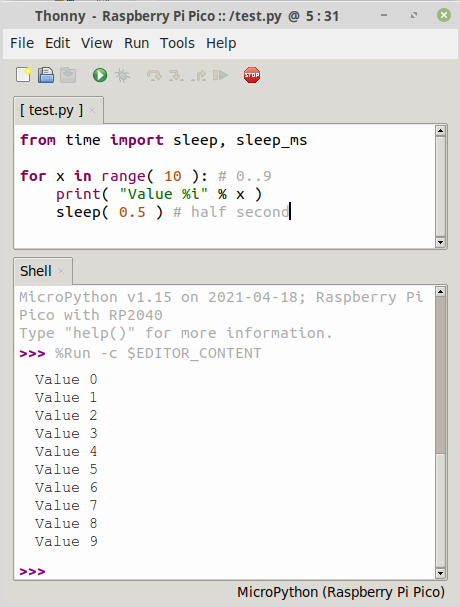
This first example how to output text with print() and wait a moment with sleep() .
Everything you will print() will be sent to REPL (so over the USB-Serial line) and being visible in Thonny.
This is incredibly useful to debug your software!
from time import sleep, sleep_ms

for x in range( 10 ): # 0..9
    print( "Value %i" % x )
    sleep( 0.5 ) # half second
You can also sleep for milliseconds with sleep_ms(x).
Control an output
The onboard LED is tied to the GPIO 25. Here how to control it.
from machine import Pin
led = Pin(25, Pin.OUT)
led.value(1) # Switch on the LED
led.value(0) # Switch off the LED
This will work the same with any GPIO pins.
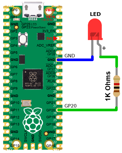
In this next example, a RED is LED wired to GP20 could be controled by modifying only one line of code.
from machine import Pin
led = Pin(20, Pin.OUT)
led.value(1) # Switch on the LED
led.value(0) # Switch off the LED
Tips & tricks:
- LEDs are polarized component, they work only if wired the right way.
- The longer LED pin is the "+" sign.
- Don't use blue LED, their forward voltage is too close from 3V to make them lightning.
- This assembly "source" the required current to the LED.
Input Reading
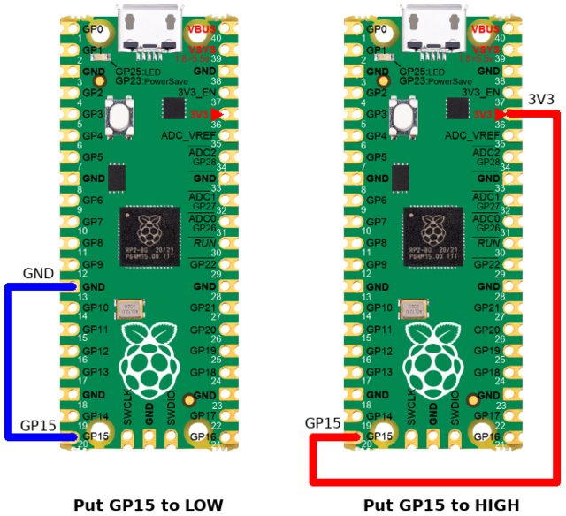
The following code will read the state of the GP15 configured as input pin.
>>> from machine import Pin
>>> p = Pin( 15, Pin.IN )
>>> p.value()
0                <--- Pin tied to GND
>>> p.value()
1                <--- Pin tied to 3.3V
| When the Pin is neither tied to GND, neither to 3.3V, then the pin voltage is said "floating". |
The logical state of a floating pin is unpredictable, it may be High, it may be Low... we don't know.
To avoids that issue, the best is to use a pull-up resistor. Many microcontroler have internal pull-up resistor (it just needs to be activated).
Input Reading with Pull-Up
The pico can activates a Pull-up resistor on any of its input pins.
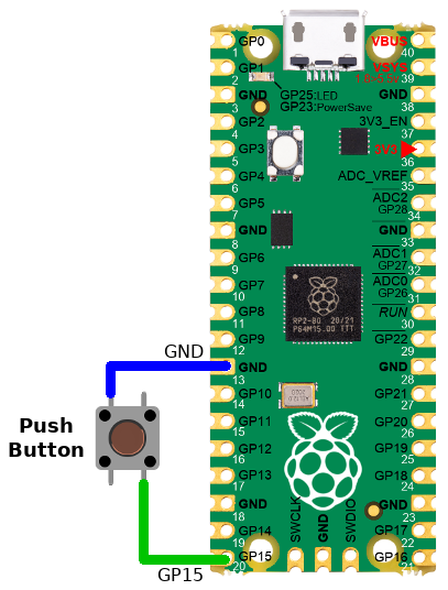
When the Pin is tied to ground then the input is Low (0) otherwise, the pull-up resistor will drive back the pin voltage to 3.3V.
The following code will read the state of the GP15 configured as input pin + pull-up.
>>> from machine import Pin
>>> p = Pin( 15, Pin.IN, PIN.PULL_UP )
>>> p.value()
0                <--- Pin tied to GND
>>> p.value()
1                <--- Pin tied to 3.3V or floating.
Analog Reading
Analog pins are able to read voltage between 0 and 3.3V.
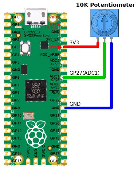
Lets read some voltage from the ADC1 (attached to GPIO 27).
The value is read on the ADC via the common read_u16() method.
That method returns a 16 bits value, so a number between 0 and 65535.
| Even if the read_u16() returns a 16 bits values, the effective ADC resolution is still 12 bits. The MicroPython internal will just upscale the ADC value from 0..4095 to returned value 0..65535 by applying a multiplier. The effective ADC reading precision is 3.3V/4095 = 0.000805V (0.8mv) |
from machine import Pin, ADC
p = Pin( 27 )
analog = ADC( p )
#
# Read the ADC value
value = analog.read_u16()
print( 'value: %i' % value )
#
# Transform into volts
volts = 3.3*value/65535
print( 'Volts: %f' % volts )
This may produce the following output in the REPL.
value: 8706
Volts: 0.438389
PWM Output
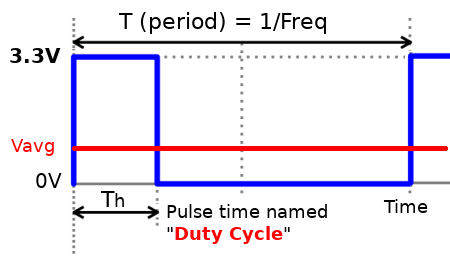
PWM stand for Pulse Width Modulation.
PWM is a method for reducing the average power delivered by an electrical signal. The average voltage that feds the load is controlled by fastly switching on & off the power between supply and load.
| PWM is abusively named "Analog Output" but don't be fooled by this expression, PWM is not a True analog output (like DAC is). |
The average voltage (average power) of PWM signal depend on the duty cycle: Vavg = 3.3V * Th / T
Obviously, a 0% duty cyle is equivalent to a LOW signal whereas a 100% duty cycle is a HIGH signal.
In the following example, we will use PWM to dim the light on the onbloard LED.
The onboard LED is tied to the GPIO 25 (and PWM will work there as with other GPIOs).
Thank to PWM we can effectively control the LED luminosity (very low duty cycle will dim the light while highest duty cycle will make it brightest).
from machine import Pin, PWM
pwm25 = PWM( Pin(25) )
pwm.duty_u16( 65534 ) # 100%
pwm.duty_u16( 32767 ) # 50%
pwm.duty_u16( 0 ) # 0% = LOW
Notes:
- PWM class must have a Pin instance as argument.
- duty_u16() must have an 16 bits integer value (0 to 65534) for the duty cycle.
- The effective Max duty_u16() value is 65534. A regression bug would make the 65535 (real max of 16 bits) equivalent to 0 !?!?!... this Phenix bug is coming back again and again.
Hardware buses
I2C Bus
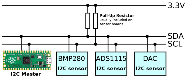
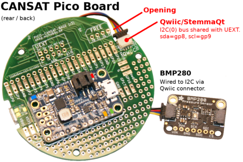
An I2C bus is a very popular serial bus in electronic to connect sensors and electronics to a microcontroler. Some DIY Maker companies did also use some "normalized" connectors around I2C bus. You may probably already ear words about Qwiic from SparkFun, StemmaQt from Adafruit (Qwiic compatible), Grove from SeeedStudio.
Maybe not the fastest bus, this bus is easy to wire and to manage and requires only 2 wires:
- SDA: Serial Data
- SCL: Serial Clock
The I2C protocol use an address (0..127) to contact the target board with request and waiting for response. For sure each sensor boards must have an unique address on the I2C. On I2C implementation, the microcontroler do always keeps the control over the I2C communication.
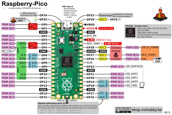
The Pico do have several I2C bus as mentionned on the PinOut diagram, look for the blue boxes.
| We do highly recommend to use the I2C(0) bus as it is connected to kit Qwiic connector and UEXT connector. |
from machine import I2C

i2c = I2C( 0 ) # sda=GP8, scl=GP9 @ 400 KHz (default)
# i2c = I2C( 0, freq=100000 ) # Reduce bus speed @ 100 KHz
More information about I2C bus on the official MicroPython I2C documentation.
You may find lot of sensor driver:
- Plateform Agnostic MicroPython Driver (esp8266-upy) (MCHobby, GitHub)
- Programs, Libraries and tools (MicroPython Forums)
- Awesome MicroPython (awesome-micropython.com)
UART Bus
The UART is often compared to a serial port (which is in facts very similar to).
It allows to send and receives data from a device using the same interface like modem, GPS, terminal. UART/Serial ports are used to creates point to point communication.
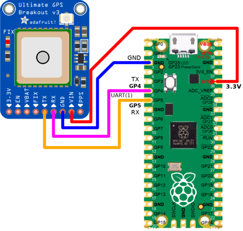
When wiring an UART, the RX & TX connection must be cross-over like the wiring to GPS here below (see the gps-ultimate MicroPython library)
| It is advised to use the UART(0) on GP0 & GP1. Indeed, UART(1) overlaps the SPI(0) used for Radio module. Alternative UART(1) position overlaps the I2C(0) bus. See the Pinout for details. |
from machine import UART, Pin

# UART(0) on GP0 & GP1
uart = UART( 0, baudrate=9600)

# UART(1) on GP4 & GP5
uart = UART( 1, baudrate=9600, timeout=3000)

# Alternate position for UART(1) by using Bus Fabric feature
uart = UART( 1, rx=Pin(9), tx=Pin(8), baudrate=9600 )
Outside of connecting device (like GPS) to the UART, you can also use an UART to get the REPL over it (exactly like USB connexion but over an UART. This may be kindly useful to bring a REPL connectivity over mobile network/device.
The following snip of code duplicates the REPL over the UART(0) .
from machine import UART
from os import dupterm

uart = UART(0, baudrate=19200, bits=8, parity=None, stop=1)
os.dupterm( uart, 1 ) # Pico Firmware must be recompile with dupterm()
The UART class is fully described into MicroPython documentation.
The dupterm() function is described here into the MicroPython documentation.
Tips & Tricks:
- One of the key parameter of UART is the timeout parameter which indicates the timeout (in ms) to receive the end-of-line on UART.readline() .
- See this Raspberry-Pi forum thread to compile a dupterm() enabled firmware for Pico.
SPI Bus
An SPI bus is high speed full duplex bus.
- High speed means several mega-hertz (can be up to +20 MHz).
- Full duplex means communicates in both direction at the same time.
Thanks to its high throughput, the SPI bus are used for display, data acquisition, data transmission, etc.
| The Cansat RFM69 Radio module of Cansat kit do use SPI(0) bus to exchange data with the MicroControler. |
SPI bus are short (below 10cm) and uses 3 wires for the data bus + a "Slave Select" wire per device:
- MOSI: Master Out Slave In. Communication from the microcontroler to the device.
- MISO: Master In Slave Out. Communication from the device to the microcontroler.
- SCLK: Clock signal giving the rythme to the data transfer.
- SS: Slave Select (activated at LOW) used to activate the device on the bus. It is also used to start "transaction" with the device.
The following snip of code creates an instance of the SPI(0) bus
from machine import Pin, SPI

ss = Pin( 5, Pin.OUT, value=1 ) # Slave Select in deactivated state by default.
# SPI(0) : GP4=Miso, GP5=/SS, GP6=Sck, GP7=Mosi
# reducing clock speed to 400 KHz
spi = SPI( 0, baudrate=400000 )
Tips & Tricks:
Under MicroPython the SS pin is not "hardware" tied to a given SPI bus. User can freely choose any pin as "Slave Select" pin.
Additional tutorials
Anyway, the followings are also goods and complete references.
Written by Meurisse D. for MCHobby

