Différences entre versions de « ENG-CANSAT-PICO-MISSION1-CAPTURE »
| (24 versions intermédiaires par le même utilisateur non affichées) | |||
| Ligne 10 : | Ligne 10 : | ||
* Air pressure | * Air pressure | ||
and transmitting the information via the RFM69HCW radio module. | and transmitting the information via the RFM69HCW radio module. | ||
| + | |||
| + | == With Cansat Kit V2 == | ||
| + | The CANSAT-BASE board of {{pl|2824|Kit Cansat Kit V2}} does already contains power regulation and the radio circuitry. | ||
| + | |||
| + | {{traduction}} | ||
| + | === Wire the barometric sensor === | ||
| + | The CANSAT-BASE does already fits a StemmaQt/Qwiic connector. Just connect the Qwiic/StemmaQt wires between the board and the sensor. | ||
| + | |||
| + | The BMP280 is wired to the Pico via the Qwiic connector, so it is connected to the {{fname|I2C(0)}} bus. | ||
| + | |||
| + | [[Fichier:ENG-CANSAT-V2-BMP280-QWIIC-01.jpg|480px]] | ||
| + | |||
| + | === Wire the temperature sensor === | ||
| + | Then connect the TMP36 analog sensor as follows: | ||
| + | * The pin 1 (on the left) to a power source (3.3V), | ||
| + | * The pin 3 (the the right) to the ground/GND. | ||
| + | * The pin 2 (middle one) to the ADC0 (GP26) analog input. | ||
| + | |||
| + | The breakout line can be used to solder the temperature sensor, the Analog Grove connector can also be used for quick connection on the board. | ||
| + | |||
| + | [[Fichier:ENG-CANSAT-V2-TMP36-ON-BREAKOUT-10.jpg|560px]] | ||
| + | |||
| + | [[Fichier:ENG-CANSAT-V2-TMP36-ON-ANALOG-GROVE-10.jpg|560px]] | ||
== Wiring on a Pico == | == Wiring on a Pico == | ||
| Ligne 44 : | Ligne 67 : | ||
|- | |- | ||
| MOSI | | MOSI | ||
| − | | GP7 ( | + | | GP7 (Mosi) |
|- | |- | ||
| MISO | | MISO | ||
| − | | GP4 ( | + | | GP4 (Miso) |
|- | |- | ||
| SCK | | SCK | ||
| Ligne 59 : | Ligne 82 : | ||
|} | |} | ||
| − | == | + | == With Cansat Kit V1 == |
=== Wire the barometric sensor === | === Wire the barometric sensor === | ||
| Ligne 84 : | Ligne 107 : | ||
Finally wire the RFM69HCW radio as follows | Finally wire the RFM69HCW radio as follows | ||
| − | [[Fichier:ENG-CANSAT-PICO-RFM69HCW-to-Cansat-Pico-Base.jpg|640px]] | + | [[Fichier:ENG-CANSAT-PICO-RFM69HCW-to-Cansat-Pico-Base-fixed.jpg|640px]] |
{| class="wikitable" | {| class="wikitable" | ||
| Ligne 103 : | Ligne 126 : | ||
| keep the same pin as receiver.<br />Otherwise use UEXT 10 (=gp10) | | keep the same pin as receiver.<br />Otherwise use UEXT 10 (=gp10) | ||
|- | |- | ||
| − | | | + | | MISO |
| 7 | | 7 | ||
| | | | ||
| GP4 = MISO | | GP4 = MISO | ||
|- | |- | ||
| − | | | + | | MOSI |
| 8 | | 8 | ||
| | | | ||
| Ligne 132 : | Ligne 155 : | ||
The code is available for download on the [https://github.com/mchobby/cansat-belgium-micropython GitHub associated to this wiki]. | The code is available for download on the [https://github.com/mchobby/cansat-belgium-micropython GitHub associated to this wiki]. | ||
| − | {{download-box|Téléchargez Mission1 Cansat Emitter script (cansat.py)|https:// | + | {{download-box|Téléchargez Mission1 Cansat Emitter script (cansat.py)|https://github.com/mchobby/cansat-belgium-micropython/blob/main/mission1/cansat.py}} |
Without any comments, extra lines and print statement (used to debug), the script makes 33 lines long for the full fledged features. | Without any comments, extra lines and print statement (used to debug), the script makes 33 lines long for the full fledged features. | ||
| Ligne 201 : | Ligne 224 : | ||
[[Fichier:ENG-CANSAT-PICO-MISSION1-CAPTURE-25.png|360px]] | [[Fichier:ENG-CANSAT-PICO-MISSION1-CAPTURE-25.png|360px]] | ||
| − | The | + | The [https://github.com/mchobby/cansat-belgium-micropython/tree/main/mission1 cansat2.py] script do re-enforce error controls with {{fname|try...except}} statements in the script and showing various onboard LED patterns in case of error. |
Error Code are reported as quick serie of blink following by slow blink... counting the slow blink gives the error code number. | Error Code are reported as quick serie of blink following by slow blink... counting the slow blink gives the error code number. | ||
| Ligne 244 : | Ligne 267 : | ||
* Send it over the USB-serial connection | * Send it over the USB-serial connection | ||
* Send it over the radio link | * Send it over the radio link | ||
| + | |||
| + | First, the script will includes all the needed libraries. | ||
| + | |||
| + | <syntaxhighlight lang="python">from machine import SPI, I2C, Pin, ADC | ||
| + | from rfm69 import RFM69 | ||
| + | from bme280 import BME280, BMP280_I2CADDR | ||
| + | import time | ||
| + | </syntaxhighlight> | ||
| + | |||
| + | This section is immediately followed by the various CONSTANT used in the script. | ||
| + | |||
| + | <syntaxhighlight lang="python">FREQ = 433.1 | ||
| + | ENCRYPTION_KEY = b"\x01\x02\x03\x04\x05\x06\x07\x08\x01\x02\x03\x04\x05\x06\x07\x08" | ||
| + | NODE_ID = 120 # ID of this node | ||
| + | BASESTATION_ID = 100 # ID of the node (base station) to be contacted | ||
| + | </syntaxhighlight> | ||
{{dbox-orange|Don't forget to update the radio frequency '''FREQ''' and the '''ENCRYPTION_KEY''' encryption key. }} | {{dbox-orange|Don't forget to update the radio frequency '''FREQ''' and the '''ENCRYPTION_KEY''' encryption key. }} | ||
| − | + | === Creating ressources === | |
| + | Then we create the needed buses resources to access the various sensor. | ||
| + | |||
| + | <syntaxhighlight lang="python">spi = SPI(0, mosi=Pin(7), miso=Pin(4), sck=Pin(6), baudrate=50000, polarity=0, phase=0, firstbit=SPI.MSB) | ||
| + | nss = Pin( 5, Pin.OUT, value=True ) | ||
| + | rst = Pin( 3, Pin.OUT, value=False ) | ||
| + | i2c = I2C(0, sda=Pin(8), scl=Pin(9) ) | ||
| + | </syntaxhighlight> | ||
| + | |||
| + | Next we create the RFM69 radio object (named {{fname|rfm}}) and the BMP280 radio object (named {{fname|bmp}}). | ||
| + | |||
| + | <syntaxhighlight lang="python"># RFM Module | ||
| + | rfm = RFM69( spi=spi, nss=nss, reset=rst ) | ||
| + | rfm.frequency_mhz = FREQ | ||
| + | rfm.encryption_key = ( ENCRYPTION_KEY ) | ||
| + | rfm.node = NODE_ID # This instance is the node 120 | ||
| + | rfm.destination = BASESTATION_ID # Send to specific node 100 | ||
| + | # BMP280 (uses the BME280) | ||
| + | bmp = BME280( i2c=i2c, address=BMP280_I2CADDR ) | ||
| + | </syntaxhighlight> | ||
| + | |||
| + | At the end of initialization section, we do creates the instances for the analog reading (the TMP36, named {{fname|adc}}) and LED controling (named {{fname|led}}). | ||
| + | |||
| + | <syntaxhighlight lang="python"># TMP36 analog pin | ||
| + | adc = ADC(Pin(26)) | ||
| + | # Onboard LED | ||
| + | led = Pin(25, Pin.OUT) | ||
| + | </syntaxhighlight> | ||
| + | |||
| + | === Information logging === | ||
| + | |||
| + | Just before the main loop, the script print the essential data. | ||
| + | |||
| + | <syntaxhighlight lang="python"># Main Loop | ||
| + | print( 'Frequency :', rfm.frequency_mhz ) | ||
| + | print( 'encryption :', rfm.encryption_key ) | ||
| + | print( 'NODE_ID :', NODE_ID ) | ||
| + | print( 'BASESTATION_ID:', BASESTATION_ID ) | ||
| + | print( '***HEADER***' ) | ||
| + | print( ":iteration_count,time_sec,pressure_hpa,tmp36_temp,bmp280_temp;" ) | ||
| + | print( '***DATA***' ) | ||
| + | </syntaxhighlight> | ||
| + | |||
| + | === Main Loop execution === | ||
| + | The main loop is composed of an infinite {{fname|while}} loop. | ||
| + | |||
| + | <syntaxhighlight lang="python"># Iteration counter | ||
| + | counter = 1 | ||
| + | # ctime contains the time (in seconds) when the script was stared | ||
| + | ctime = time.time() # Now | ||
| + | while True: | ||
| + | # Main Loop body | ||
| + | ... | ||
| + | ... | ||
| + | ... | ||
| + | counter += 1 # increment iteration counter | ||
| + | time.sleep(0.4) # wait 0.4 second between iterations | ||
| + | </syntaxhighlight> | ||
| + | |||
| + | The '''Mainloop body''' executes the following steps: | ||
| + | # Reading the sensors data | ||
| + | # Preparing the message | ||
| + | # Sending message | ||
| + | ## Switch on the onboard LED | ||
| + | ## Log message | ||
| + | ## Send message | ||
| + | ## Turn of the LED | ||
| + | |||
| + | {{underline|'''Reading sensor data:'''}} | ||
| + | |||
| + | Reading the BMP280 sensor data relies on the {{fname|bme280.py} library previously detailled. | ||
| + | |||
| + | Reading the temperature from TMP36 relies on analog reading and some conversion calculation. | ||
| + | |||
| + | <syntaxhighlight lang="python"># read BMP280 | ||
| + | t,hpa,rh = bmp.raw_values # Temp, press_hPa, humidity | ||
| + | # Read tmp36 (analog) | ||
| + | value = adc.read_u16() | ||
| + | mv = 3300.0 * value / 65535 | ||
| + | temp = (mv-500)/10 | ||
| + | </syntaxhighlight> | ||
| + | |||
| + | Next the mainloop do prepare the string message (variable {{fname|msg}} by using the powerful Python string formatting feature. | ||
| + | |||
| + | {{underline|'''Formatting data:'''}} | ||
| + | |||
| + | This can be done with one single line. Notice the expression {{fname|time.time()-ctime}} calculating the elapse time (in second) since the mainloop started. | ||
| + | <syntaxhighlight lang="python"># message: iteration_count,time_sec,pressure_hpa,tmp36_temp,bmp280_temp (coma separated) | ||
| + | msg = ":%i,%i,%6.2f,%5.2f,%5.2f;" % (counter,time.time()-ctime,hpa,temp,t) | ||
| + | </syntaxhighlight> | ||
| + | |||
| + | {{underline|'''Sending data:'''}} | ||
| + | |||
| + | The onboard LED is switched on during data transmission (and print). This makes the LED flashing briefly while data us transmitted. | ||
| + | |||
| + | The data packet are sent without ACK, this would avoids unnecessary latency by waiting for ACK. Indeed, the Cansat will not modifies its behaviours if the data are not received on the ground station. | ||
| + | |||
| + | <syntaxhighlight lang="python">led.on() # Led ON while sending data | ||
| + | print( msg ) | ||
| + | # Send a packet without ACK - Send it, don't care if it is received or not | ||
| + | rfm.send(bytes(msg , "utf-8") ) | ||
| + | led.off() | ||
| + | </syntaxhighlight> | ||
| + | |||
| + | Just to remind, the {{fname|rfm.send()}} only accepts binary data as generated with bytes() or bytearray(). The message string must be converted to a binary with {{fname|bytes()}}. As binary data does not accept value > 127 without a proper encoding then the bytes() conversion must identifies the encoding of the source string to applies the adequate encoding scheme (UTF8 -> Binary). | ||
== Fault tolerant design == | == Fault tolerant design == | ||
Version actuelle datée du 2 août 2025 à 20:00
Introduction
| Before starting this point, we recommend to follow all the sensors testing steps (BMP280 sensor, TMP36 Sensor, RFM69HCW radio, RFM69HCW Testing). It contains all the details about the wiring, install needed libraries and conduct basic testing. |
The following Wiring is used to capture
- Air temperature
- Air pressure
and transmitting the information via the RFM69HCW radio module.
With Cansat Kit V2
The CANSAT-BASE board of Kit Cansat Kit V2 does already contains power regulation and the radio circuitry.
Wire the barometric sensor
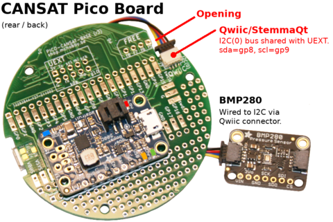
The CANSAT-BASE does already fits a StemmaQt/Qwiic connector. Just connect the Qwiic/StemmaQt wires between the board and the sensor.
The BMP280 is wired to the Pico via the Qwiic connector, so it is connected to the I2C(0) bus.
Wire the temperature sensor
Then connect the TMP36 analog sensor as follows:
- The pin 1 (on the left) to a power source (3.3V),
- The pin 3 (the the right) to the ground/GND.
- The pin 2 (middle one) to the ADC0 (GP26) analog input.
The breakout line can be used to solder the temperature sensor, the Analog Grove connector can also be used for quick connection on the board.
Wiring on a Pico
Wire the barometric sensor
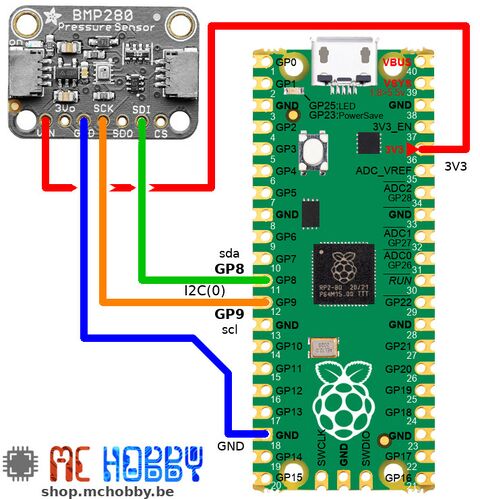
The BMP280 is wired on the I2C bus of the Pico.
Wire the temperature sensor
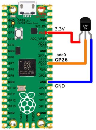
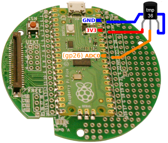
Then connect the TMP36 sensor as follows:
- The pin 1 (on the left) to a power source (3.3V),
- The pin 3 (the the right) to the ground/GND.
- The pin 2 (middle one) to the ADC0 (GP26) analog input.
Wire the radio module
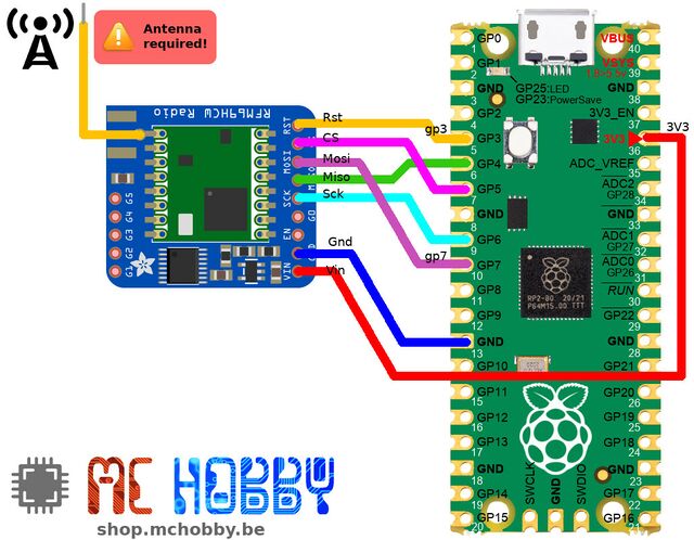
Finally wire the RFM69HCW radio as follows:
Here is the description of wiring between the Pico and the RFM69 module.
| RFM69HCW | PICO |
|---|---|
| RST |
GP3 |
| CS | GP5 (Slave Select) |
| MOSI | GP7 (Mosi) |
| MISO | GP4 (Miso) |
| SCK | GP6 (Clock) |
| GND | GND |
| VIN | 3V3 |
With Cansat Kit V1
Wire the barometric sensor
The Kit Cansat avec Pico does already fire a StemmaQt/Qwiic connector. Just connect the Qwiic/StemmaQt wires between the board and the sensor. The Qwiic connector is wired to the I2C(0) bus.
The BMP280 is wired to the Pico via the Qwiic connector.
Wire the temperature sensor
Then connect the TMP36 sensor as follows:
- The pin 1 (on the left) to a power source (3.3V),
- The pin 3 (the the right) to the ground/GND.
- The pin 2 (middle one) to the ADC0 (GP26) analog input.
The Pico pad on the board are large enough to quickly solder the TMP36 on the board. The TMP36 can also bee soldered under the board.
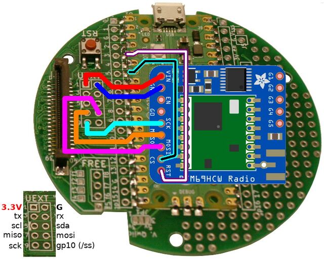
Wire the radio module
| The RFM69HCW radio module can be soldered above or below the base board (depending on your needs). |
Finally wire the RFM69HCW radio as follows
| RFM69HCW | UEXT pin | PICO | Remark |
|---|---|---|---|
| RST | GP3 | ||
| CS | GP5 | keep the same pin as receiver. Otherwise use UEXT 10 (=gp10) | |
| MISO | 7 | GP4 = MISO | |
| MOSI | 8 | GP7 = MOSI | |
| SCK | 9 | GP6 = SCK | |
| GND | 2 | PICO GND | |
| VIN | 1 | PICO 3.3V |
Download the code
The code is available for download on the GitHub associated to this wiki.
Without any comments, extra lines and print statement (used to debug), the script makes 33 lines long for the full fledged features.
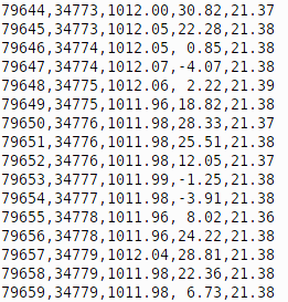
As showned in the following picture, the intermediate script testing runs for about 80.000 iterations and message sending without an issue.
About testing
Now, we will move forward in several steps.
- Getting data from sensors + send them it over the REPL/Shell connection (to confirm good working) + transmit over radio
- Testing the radio reception
- Going autonomous + add the Lipo
The code proposed here under has been tested up to 80000 iterations without issue, time when we decided to ends the test :-) .
Once the script uploaded to your Pico, open the REPL/Shell over the USB-serial (with Thonny, Putty, MPRemote). The script can be started from REPL with import cansat .
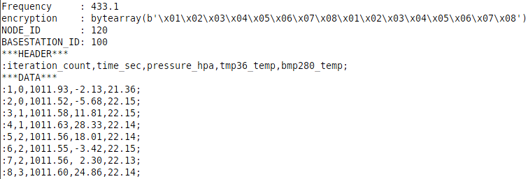
You should see the following messages appears on the Serial Monitor.
Where we could see the transmitted messages with the iteration counter, timing and data.
| The ACKnowledgement feature is disabled to avoids unnecessary latency when waiting back for ACK response (which may never comes back in the case of a CanSat in high altitude). |
Structuring the data
The radio module only sends buffer of binary data to the receiver. This is a bit rough but efficient.
So to transport the data to the receiver, we need to transform the values (float, integer) into their string representation.
When having multiple data in their string representation is not enough, they must also been organized.
The final format must be easy to parse and very compact (smaller is the radio message and higher is the chance for him to get to the ground without error).
We propose the following format:
:data1,data2,data3,data4;
where:
- : is the begin of data stream
- ; is the end of data stream
- , is the separator between data items (like CSV format).
- datax are the string representation of the various data. The characters ;:, are forbidden in this area.
It is recommend to include the following:
- counter as data1. counter is a simple numeric variable incremented of one unit after each transmission. This would allow the receiver to detect lost message (since it would exist holes in the numbering of received messages).
- time_sec as data2. This would help to create timing chart or time based data analysis. We suggest to use the time.time() function which count the number of seconds since the last microcontroler reset.
As explained later in the code the msg variable contains the message to be transmitted to the ground. The python language offers facilities to format string and transform typed data to their string representation.
msg = ":%i,%i,%6.2f,%5.2f,%5.2f;" % (counter,time.time()-ctime,hpa,temp,t)
print( msg )
# Send over RFM69HCW module
rfm.send( bytes(msg , "utf-8") )
The ":%i,%i,%6.2f,%5.2f,%5.2f;" string formating use %i to format an integer and %6.2f or %5.2f to format floating point value. The parameter to be formatted are given with the tuple (having 5 entries) just being the % sign.
As the rfm.send() only acept bytes/binary data, the msg is transformed into an array of bytes with bytes() . bytes() array can only contains ASCII bytes < 127, any other character/byte must be appropriately encoded! This is why the call to bytes(msg , "utf-8") mentions the source string encoding (which is UTF-8 nowadays).
LEDs and Error management
Being able to understand rapidly what's happening inside your object is essential to rapidly fix the issue.
The best is to figure out what's happening is to use LED, blink status, heartbeat.
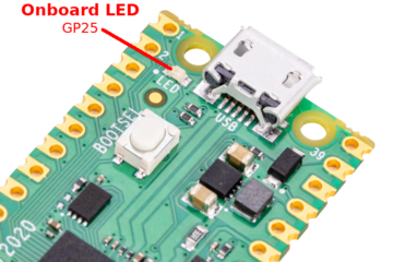
By doing so, no need to attach an USB cable and opens a terminal over the USB-Serial to figure out the status of the object.
The cansat2.py script do re-enforce error controls with try...except statements in the script and showing various onboard LED patterns in case of error.
Error Code are reported as quick serie of blink following by slow blink... counting the slow blink gives the error code number.
| LED operation | Description | Fix the issue |
| OFF (continuously) | No code is running/started. | Check that cansat code is called/executed from main. |
| Short blink | The radio is emitting data. | The software is running properly and emitting data. |
| Error 1 | RFM69 Radio module initialisation error | Double check the RFM69 wiring. Check wiring vs pins declaration (in code) |
| Error 2 | BMP280 initialisation error | Double check the BMP280 wiring. |
| Error 3 | BMP280 read data error. | Double check stability of I2C bus. |
| Error 4 | Main application loop crash unexpectedly | Check error description description in the REPL console. |
The code explained
Here some explanation about the cansat.py script used in the CanSat.
This MicroPython script would:
- Initialize the buses and hardware
- Collect the sensor data
- Send it over the USB-serial connection
- Send it over the radio link
First, the script will includes all the needed libraries.
from machine import SPI, I2C, Pin, ADC
from rfm69 import RFM69
from bme280 import BME280, BMP280_I2CADDR
import time
This section is immediately followed by the various CONSTANT used in the script.
FREQ           = 433.1
ENCRYPTION_KEY = b"\x01\x02\x03\x04\x05\x06\x07\x08\x01\x02\x03\x04\x05\x06\x07\x08"
NODE_ID        = 120 # ID of this node
BASESTATION_ID = 100 # ID of the node (base station) to be contacted
Creating ressources
Then we create the needed buses resources to access the various sensor.
spi = SPI(0, mosi=Pin(7), miso=Pin(4), sck=Pin(6), baudrate=50000, polarity=0, phase=0, firstbit=SPI.MSB)
nss = Pin( 5, Pin.OUT, value=True )
rst = Pin( 3, Pin.OUT, value=False )
i2c = I2C(0, sda=Pin(8), scl=Pin(9) )
Next we create the RFM69 radio object (named rfm) and the BMP280 radio object (named bmp).
# RFM Module
rfm = RFM69( spi=spi, nss=nss, reset=rst )
rfm.frequency_mhz  = FREQ
rfm.encryption_key = ( ENCRYPTION_KEY )
rfm.node           = NODE_ID # This instance is the node 120
rfm.destination    = BASESTATION_ID # Send to specific node 100
# BMP280 (uses the BME280)
bmp = BME280( i2c=i2c, address=BMP280_I2CADDR )
At the end of initialization section, we do creates the instances for the analog reading (the TMP36, named adc) and LED controling (named led).
# TMP36 analog pin
adc = ADC(Pin(26))
# Onboard LED
led = Pin(25, Pin.OUT)
Information logging
Just before the main loop, the script print the essential data.
# Main Loop
print( 'Frequency     :', rfm.frequency_mhz )
print( 'encryption    :', rfm.encryption_key )
print( 'NODE_ID       :', NODE_ID )
print( 'BASESTATION_ID:', BASESTATION_ID )
print( '***HEADER***' )
print( ":iteration_count,time_sec,pressure_hpa,tmp36_temp,bmp280_temp;" )
print( '***DATA***' )
Main Loop execution
The main loop is composed of an infinite while loop.
# Iteration counter
counter = 1
# ctime contains the time (in seconds) when the script was stared
ctime = time.time() # Now
while True:
    # Main Loop body
    ...
    ...
    ...
    counter += 1    # increment iteration counter
    time.sleep(0.4) # wait 0.4 second between iterations
The Mainloop body executes the following steps:
- Reading the sensors data
- Preparing the message
- Sending message
- Switch on the onboard LED
- Log message
- Send message
- Turn of the LED
Reading sensor data:
Reading the BMP280 sensor data relies on the {{fname|bme280.py} library previously detailled.
Reading the temperature from TMP36 relies on analog reading and some conversion calculation.
# read BMP280
t,hpa,rh =  bmp.raw_values # Temp, press_hPa, humidity
# Read tmp36 (analog)
value = adc.read_u16()
mv = 3300.0 * value / 65535
temp = (mv-500)/10
Next the mainloop do prepare the string message (variable msg by using the powerful Python string formatting feature.
Formatting data:
This can be done with one single line. Notice the expression time.time()-ctime calculating the elapse time (in second) since the mainloop started.
# message: iteration_count,time_sec,pressure_hpa,tmp36_temp,bmp280_temp (coma separated)
msg = ":%i,%i,%6.2f,%5.2f,%5.2f;" % (counter,time.time()-ctime,hpa,temp,t)
Sending data:
The onboard LED is switched on during data transmission (and print). This makes the LED flashing briefly while data us transmitted.
The data packet are sent without ACK, this would avoids unnecessary latency by waiting for ACK. Indeed, the Cansat will not modifies its behaviours if the data are not received on the ground station.
led.on() # Led ON while sending data
print( msg )
# Send a packet without ACK - Send it, don't care if it is received or not
rfm.send(bytes(msg , "utf-8") )
led.off()
Just to remind, the rfm.send() only accepts binary data as generated with bytes() or bytearray(). The message string must be converted to a binary with bytes(). As binary data does not accept value > 127 without a proper encoding then the bytes() conversion must identifies the encoding of the source string to applies the adequate encoding scheme (UTF8 -> Binary).
Fault tolerant design
The goal is to transmit the data to the ground station.
The code of the Cansat Emitter (this section) and Receiver BaseStation (next section) are doing the job.
However, what would happens to your data if the antenna did break? All the data are lots!
This is where the "Data Logging" would be a great help!
As showed earlier, it is also possible to store/save the data into the MicroPython FileSystem (the Flash).
A good approach would be:
- to save the data in the file
- then send it over Radio.
In this way, the data stays available inside the CanSat and could be readed as suited.
Written by Meurisse D. for MCHobby

