Différences entre versions de « PN532-RFID-NFC-Brancher-Breakout »
| Ligne 10 : | Ligne 10 : | ||
{{ADFImage|PN532-RFID-NFC-Brancher-Breakout-00.jpg|640px}} | {{ADFImage|PN532-RFID-NFC-Brancher-Breakout-00.jpg|640px}} | ||
| − | == | + | == Brancher le Breakout en SPI == |
| − | + | Le composant PN532 et son breakout sont conçu pour être utilisé sur des systèmes 3.3V. Pour utiliser le breakout sur un système 5V tel qu'Arduino, vous devez utiliser un ''level shifter'' (un convertisseur de niveau logique) pour convertir les signaux 5V en 3.3v et vice-versa. Bien entendu, si vous disposez d'un système embarqué 3.3V vous n'aurez pas besoin d'un ''level shifter''! | |
| − | + | Pour commencer, nous allons brancher les header (connecteurs) sur le breakout board. Vous aurez besoin d'un deux sections de 3 broches et une section de 8 broches. Vous pouvez sectionner ces éléments sur un connecteur plus long. | |
{{ADFImage|PN532-RFID-NFC-Brancher-Breakout-10.jpg|640px}} | {{ADFImage|PN532-RFID-NFC-Brancher-Breakout-10.jpg|640px}} | ||
| Ligne 22 : | Ligne 22 : | ||
{{ADFImage|PN532-RFID-NFC-Brancher-Breakout-12.jpg|640px}} | {{ADFImage|PN532-RFID-NFC-Brancher-Breakout-12.jpg|640px}} | ||
| − | + | Soudez les deux petites pièces sur les emplacements SEL0 et SEL1. Ce sont les connecteurs permettant de sélectionner l'interface sur la puce. En fonction de la position des cavaliers la puce fonctionnera en Série TTL, I2C ou SPI. Soudez ensuite la section la plus longue au bout de la carte de façon à pouvoir brancher le breakout sur un breadboard. | |
{{ADFImage|PN532-RFID-NFC-Brancher-Breakout-13.jpg|640px}} | {{ADFImage|PN532-RFID-NFC-Brancher-Breakout-13.jpg|640px}} | ||
| − | + | Branchez un convertisseur de niveau logique (Level Shifter) (un 4050 dans cet exemple) pour raccorder le breakout sur un Arduino. Le détrompeur du 4050 se trouve 'au dessus' sur l'image. | |
| − | * Arduino | + | * La broche digital d'Arduino 2 est branché sur la broche 9 du 4050 (fil orange) |
| − | * Arduino | + | * La broche digital d'Arduino 3 est branché sur la broche 11 du 4050 (fil jaune) |
| − | * Arduino | + | * La broche digital d'Arduino 4 est branché sur la broche 14 du 4050 (fil vert) |
Suggestion: Vous pourriez également utiliser un {{pl|131|convertisseur de niveau logique 4 bit comme celui-ci}}. | Suggestion: Vous pourriez également utiliser un {{pl|131|convertisseur de niveau logique 4 bit comme celui-ci}}. | ||
| − | + | Sur le breakout: | |
| − | + | * '''3.3Vin''' est conné sur la broche 3.3V d'Arduino | |
| − | * '''3.3Vin''' | + | * '''SCK''' est connecté sur la broche 10 du 4050 (fil orange) |
| − | * '''SCK''' | + | * '''MISO''' is connected to Arduino pin 5 (fil bleu) |
| − | * '''MISO''' is connected to Arduino pin 5 ( | + | * '''MOSI''' est connecté sur la broche 12 du 4050 (fil jaune) |
| − | * '''MOSI''' | + | * '''SSEL''' est connecté sur la broche 15 du 4050 (fil vert) |
| − | * '''SSEL''' | + | * '''GND''' est connecté sur la masse/GND d'Arduino (fil noir) |
| − | * '''GND''' | ||
Also connect 4050 pin #1 to 3.3V and pin #8 to ground. | Also connect 4050 pin #1 to 3.3V and pin #8 to ground. | ||
| Ligne 51 : | Ligne 50 : | ||
Also, we need to select SPI as the interface so on '''SEL1''' place the jumper in the '''ON''' position. for '''SEL0''' place the jumper in the '''OFF''' position. | Also, we need to select SPI as the interface so on '''SEL1''' place the jumper in the '''ON''' position. for '''SEL0''' place the jumper in the '''OFF''' position. | ||
| − | That's it! Later on you can change what Arduino pins you are using but for the beginning test we suggest matching our wiring. | + | That's it! Later on you can change what Arduino pins you are using but for the beginning test we suggest matching our wiring. |
== Utilisation en I2C == | == Utilisation en I2C == | ||
Version du 25 juillet 2015 à 14:14
Le breakout PN532
Cette section du tutoriel se concentre spécifiquement sur le Breakout board. Nous montrons comment utiliser la connexion SPI. Le breakout board support la connexion série TTL et I2C. Il n'y a pas de tutoriel se concentrant sur l'usage série ou I2C puisque SPI est la méthode de communication Cross-Plateforme par excellence.
Si vous voulez utiliser la version Shield, voyez la page suivante
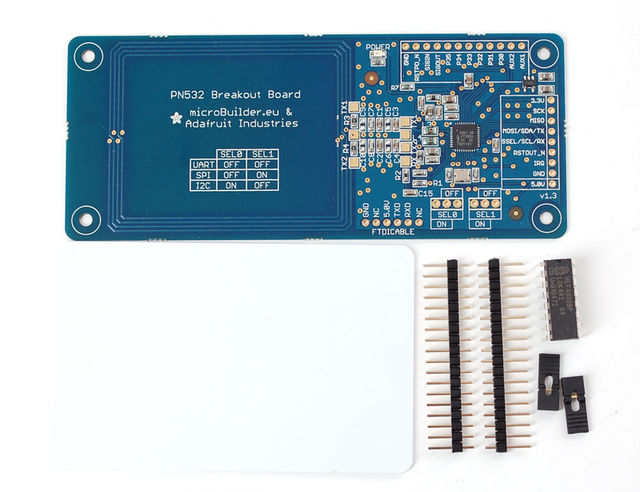
Crédit: AdaFruit Industries www.adafruit.com
Brancher le Breakout en SPI
Le composant PN532 et son breakout sont conçu pour être utilisé sur des systèmes 3.3V. Pour utiliser le breakout sur un système 5V tel qu'Arduino, vous devez utiliser un level shifter (un convertisseur de niveau logique) pour convertir les signaux 5V en 3.3v et vice-versa. Bien entendu, si vous disposez d'un système embarqué 3.3V vous n'aurez pas besoin d'un level shifter!
Pour commencer, nous allons brancher les header (connecteurs) sur le breakout board. Vous aurez besoin d'un deux sections de 3 broches et une section de 8 broches. Vous pouvez sectionner ces éléments sur un connecteur plus long.
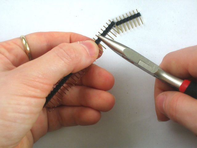
Crédit: AdaFruit Industries www.adafruit.com
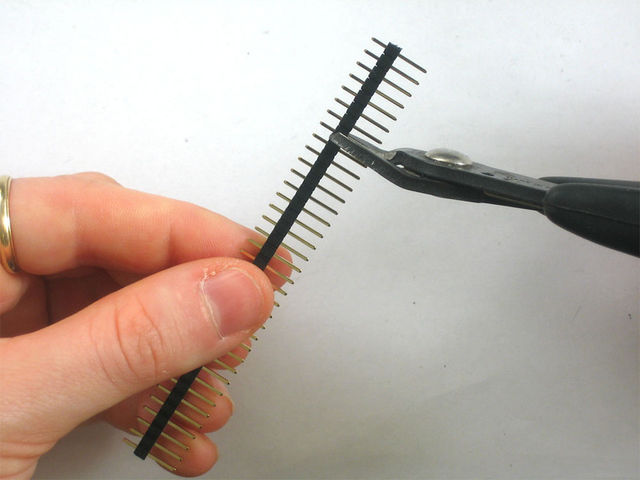
Crédit: AdaFruit Industries www.adafruit.com
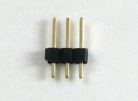
Crédit: AdaFruit Industries www.adafruit.com
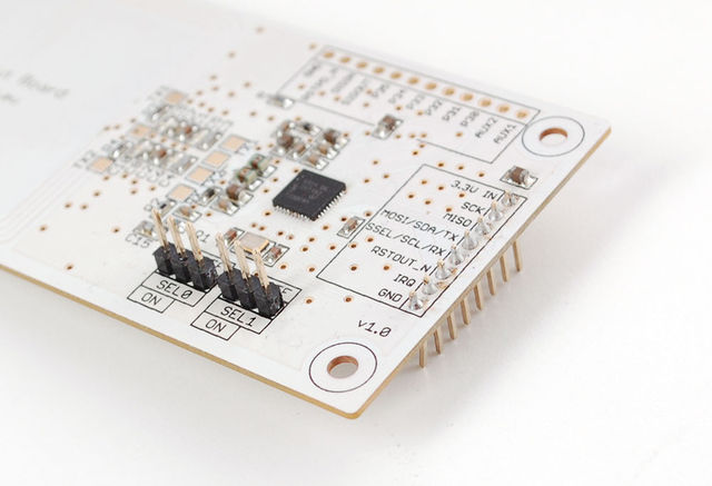
Soudez les deux petites pièces sur les emplacements SEL0 et SEL1. Ce sont les connecteurs permettant de sélectionner l'interface sur la puce. En fonction de la position des cavaliers la puce fonctionnera en Série TTL, I2C ou SPI. Soudez ensuite la section la plus longue au bout de la carte de façon à pouvoir brancher le breakout sur un breadboard.
Crédit: AdaFruit Industries www.adafruit.com
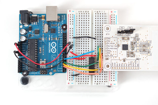
Branchez un convertisseur de niveau logique (Level Shifter) (un 4050 dans cet exemple) pour raccorder le breakout sur un Arduino. Le détrompeur du 4050 se trouve 'au dessus' sur l'image.
- La broche digital d'Arduino 2 est branché sur la broche 9 du 4050 (fil orange)
- La broche digital d'Arduino 3 est branché sur la broche 11 du 4050 (fil jaune)
- La broche digital d'Arduino 4 est branché sur la broche 14 du 4050 (fil vert)
Suggestion: Vous pourriez également utiliser un convertisseur de niveau logique 4 bit comme celui-ci.
Sur le breakout:
- 3.3Vin est conné sur la broche 3.3V d'Arduino
- SCK est connecté sur la broche 10 du 4050 (fil orange)
- MISO is connected to Arduino pin 5 (fil bleu)
- MOSI est connecté sur la broche 12 du 4050 (fil jaune)
- SSEL est connecté sur la broche 15 du 4050 (fil vert)
- GND est connecté sur la masse/GND d'Arduino (fil noir)
Also connect 4050 pin #1 to 3.3V and pin #8 to ground.
Click to see a larger image. The red power wire should be connected to the 3.3v pin on the Arduino!
Crédit: AdaFruit Industries www.adafruit.com
Also, we need to select SPI as the interface so on SEL1 place the jumper in the ON position. for SEL0 place the jumper in the OFF position.
That's it! Later on you can change what Arduino pins you are using but for the beginning test we suggest matching our wiring.
Utilisation en I2C
| If you are using the shield in I2C mode, you will also need to add two 1.5K pullups on the SCL/SDA lines, since the breakout and the Arduino don't include the pullups. Simply solder or add a 1.5K resistor between SCL and 3.3V, and SDA and 3.3V, and then connect the breakout as you normally would. |
Source: PN532 RFID/NFC Breakout and Shield créé par LadyAda pour AdaFruit Industries. Crédit [www.adafruit.com AdaFruit Industries]
Traduit par Meurisse D. pour MCHobby.be
Traduit avec l'autorisation d'AdaFruit Industries - Translated with the permission from Adafruit Industries - www.adafruit.com
Toute référence, mention ou extrait de cette traduction doit être explicitement accompagné du texte suivant : « Traduction par MCHobby (www.MCHobby.be) - Vente de kit et composants » avec un lien vers la source (donc cette page) et ce quelque soit le média utilisé.
L'utilisation commercial de la traduction (texte) et/ou réalisation, même partielle, pourrait être soumis à redevance. Dans tous les cas de figures, vous devez également obtenir l'accord du(des) détenteur initial des droits. Celui de MC Hobby s'arrêtant au travail de traduction proprement dit.
