Différences entre versions de « ENG-CANSAT-PICO-HowTo »
| Ligne 127 : | Ligne 127 : | ||
PWM stand for ''Pulse Width Modulation''. | PWM stand for ''Pulse Width Modulation''. | ||
| − | PWM is a method for reducing the average power delivered by an electrical signal. The average voltage that feds the load is controlled by fastly switching on & off the power between supply and load. PWM is abusively named "''Analog Output''" but don't be fooled by this expression, PWM is not a True analog output (like DAC is). | + | PWM is a method for reducing the average power delivered by an electrical signal. The average voltage that feds the load is controlled by fastly switching on & off the power between supply and load. |
| + | |||
| + | {{ambox|text=PWM is abusively named "''Analog Output''" but don't be fooled by this expression, PWM is not a True analog output (like DAC is).}} | ||
[[Fichier:ENG-CANSAT-FEATHER-PICO-pwm-01.png]] | [[Fichier:ENG-CANSAT-FEATHER-PICO-pwm-01.png]] | ||
| + | The average voltage of PWM signal depend on the duty cycle: Vavg = 3.3V * Th / P | ||
| − | The onboard LED is tied to the GPIO 25. | + | The onboard LED is tied to the GPIO 25. And that GPIO 25 can also be controled with PWM. |
| − | + | Thank to PWM we can control the effective luminosity of the LED by setting-up the duty cycle of the PWM signal. | |
<syntaxhighlight lang="python"> | <syntaxhighlight lang="python"> | ||
Version du 23 février 2022 à 23:11
MicroPython How To
This section of the tutoriel contains small portion of code explaining how to use digital pins, analog pins, buses and all the fundamentals to control the board with Python code.
Everything you learned about python language like variables, loops, conditionals, object programming, ... does applies to MicroPython.
A large part of standard Python libraries have been ported to MicroPython (partially or completely). Keep in mind that MicroControler doesn't have as much power and as much memory than a regular computer. So choice has been made: no gregorian calandar, no numpy (it exists some port anyway), no TKinter.
Print and Waits
This first example how to output text with print() and wait a moment with sleep() .
Everything you will print() will be sent to REPL (so over the USB-Serial line) and being visible in Thonny.
from time import sleep, sleep_ms

for x in range( 10 ): # 0..9
    print( "Value %i" % x )
    sleep( 0.5 ) # half second
You can also sleep for milliseconds with sleep_ms(x)
Control an output
The onboard LED is tied to the GPIO 25. Here how to control it.
from machine import Pin
led = Pin(25, Pin.OUT)
led.value(1) # Switch on the LED
led.value(0) # Switch off the LED
This will work the same with any GPIO pins.
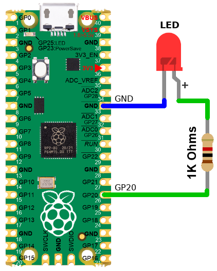
In this next example, a RED is LED wired to GP20 could be controled by modifying only one line of code.
from machine import Pin
led = Pin(20, Pin.OUT)
led.value(1) # Switch on the LED
led.value(0) # Switch off the LED
Tips & tricks:
- LEDs are polarized component, they work only if wired the right way.
- The longer LED pin is the "+" sign.
- Don't use blue LED, their forward voltage is too close from 3V to make them lightning.
- This assembly "source" the required current to the LED.
Input Reading
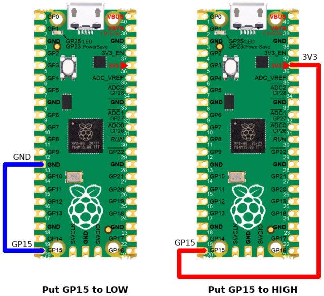
The following code will read the state of the GP15 configured as input pin.
>>> from machine import Pin
>>> p = Pin( 15, Pin.IN )
>>> p.value()
0                <--- Pin tied to GND
>>> p.value()
1                <--- Pin tied to 3.3V
| When the Pin is neither tied to GND, neither to 3.3V, then the pin voltage is said "floating". |
The logical state of a floating pin is unpredictable, it may be High, it may be Low... we don't know.
To avoids that issue, the best is to use a pull-up resistor. Many microcontroler have internal pull-up resistor (it just needs to be activated).
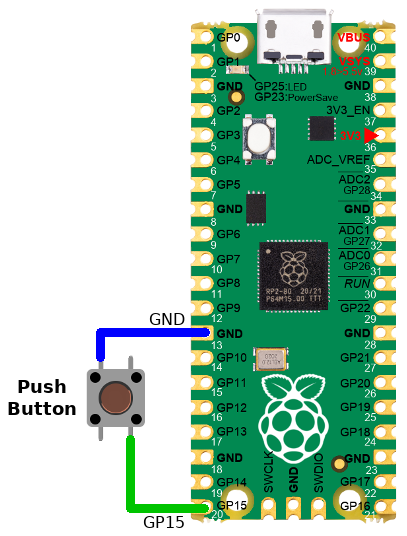
Input Reading with Pull-Up
The pico can activates a Pull-up resistor on any of its input pins.
When the Pin is tied to ground then the input is Low (0) otherwise, the pull-up resistor will drive back the pin voltage to 3.3V.
The following code will read the state of the GP15 configured as input pin + pull-up.
>>> from machine import Pin
>>> p = Pin( 15, Pin.IN, PIN.PULL_UP )
>>> p.value()
0                <--- Pin tied to GND
>>> p.value()
1                <--- Pin tied to 3.3V or floating.
Analog Reading
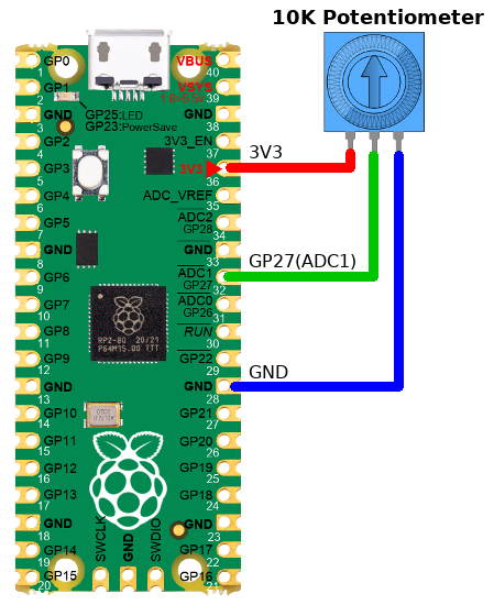
Analog pins are able to read voltage between 0 and 3.3V.
Lets read some voltage from the ADC1 (attached to GPIO 27).
The value is read on the ADC via the common read_u16() method.
That method returns a 16 bits value, so a number between 0 and 65535.
| Even if the read_u16() returns a 16 bits values, the effective ADC resolution is still 12 bits. The MicroPython internal will just upscale the ADC value from 0..4095 to returned value 0..65535 by applying a multiplier. |
from machine import Pin, ADC
p = Pin( 27 )
analog = ADC( p )
#
# Read the ADC value
value = analog.read_u16()
print( 'value: %i' % value )
#
# Transform into volts
volts = 3.3*value/65535
print( 'Volts: %f' % volts )
This may produce the following output in the REPL.
value: 8706
Volts: 0.438389
PWM Output
PWM stand for Pulse Width Modulation.
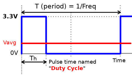
PWM is a method for reducing the average power delivered by an electrical signal. The average voltage that feds the load is controlled by fastly switching on & off the power between supply and load.
| PWM is abusively named "Analog Output" but don't be fooled by this expression, PWM is not a True analog output (like DAC is). |
The average voltage of PWM signal depend on the duty cycle: Vavg = 3.3V * Th / P
The onboard LED is tied to the GPIO 25. And that GPIO 25 can also be controled with PWM.
Thank to PWM we can control the effective luminosity of the LED by setting-up the duty cycle of the PWM signal.
from machine import Pin
x
x
x
x
Hardware buses
I2C Bus
The onboard LED is tied to the GPIO 25. Here how to control it.
from machine import Pin
x
x
x
x
UART Bus
The onboard LED is tied to the GPIO 25. Here how to control it.
from machine import Pin
x
x
x
x
SPI Bus
The onboard LED is tied to the GPIO 25. Here how to control it.
from machine import Pin
x
x
x
x
Additional tutorials
Anyway, the followings are also goods and complete references.
Written by Meurisse D. for MCHobby
