Différences entre versions de « ENG-CANSAT-PICO-MISSION1-CAPTURE »
Sauter à la navigation
Sauter à la recherche
| Ligne 21 : | Ligne 21 : | ||
* The pin 1 (on the left) to a power source (3.3V), | * The pin 1 (on the left) to a power source (3.3V), | ||
* The pin 3 (the the right) to the ground/GND. | * The pin 3 (the the right) to the ground/GND. | ||
| − | * The pin 2 (middle one) to the | + | * The pin 2 (middle one) to the ADC0 analog input. |
| − | [[Fichier:ENG-CANSAT-PICO-TMP36-01. | + | [[Fichier:ENG-CANSAT-PICO-TMP36-01.jpg|320px]] |
=== Wire the radio module === | === Wire the radio module === | ||
Version du 6 mars 2022 à 00:27
Introduction
| Before starting this point, we recommend to follow all the sensors testing steps (BMP280 sensor, TMP36 Sensor, RFM69HCW radio, RFM69HCW Testing). It contains all the details about the wiring, install needed libraries and conduct basic testing. |
The following Wiring is used to capture
- Air temperature
- Air pressure
and transmitting the information via the RFM69HCW radio module.
Wiring on a Pico
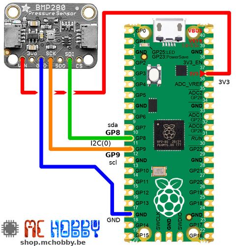
Wire the barometric sensor
The BMP280 is wired on the I2C bus of the Pico.
Wire the temperature sensor
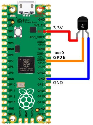
Then connect the TMP36 sensor as follows:
- The pin 1 (on the left) to a power source (3.3V),
- The pin 3 (the the right) to the ground/GND.
- The pin 2 (middle one) to the ADC0 analog input.
Wire the radio module
Finally wire the RFM69HCW radio as follows:
| Feather M0 Express | RFM69 |
| 3V | VIN |
| GND | GND |
| MO | MOSI |
| MI | MISO |
| SCK | SCK |
| 6 | CS |
| 9 | G0 |
| 10 | RST |
Written by Meurisse D. for MCHobby

