PN532-RFID-NFC-Brancher-Breakout
Le breakout PN532
|
|
En cours de traduction/élaboration. |
This part of the tutorial is specifically for the Breakout board. We show how to use it with SPI. The breakout also supports TTL serial and I2C but we don't have a tutorial for using it that way as SPI is the most cross-platform method to communicate
If you're using the shield, check the next page
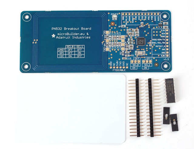
Crédit: AdaFruit Industries www.adafruit.com
Wiring the Breakout for SPI
The PN532 chip and breakout is designed to be used by 3.3V systems. To use it with a 5V system such as an Arduino, a level shifter is required to convert the high voltages into 3.3V. If you have a 3.3V embedded system you won't have to use the shifter of course!
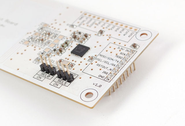
To begin, we'll solder in the header to the breakout board. You'll need two small 3-pin pieces of header and one 8-pin piece. You can break these off of a large piece.
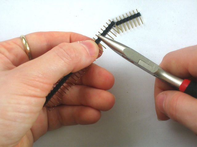
Crédit: AdaFruit Industries www.adafruit.com
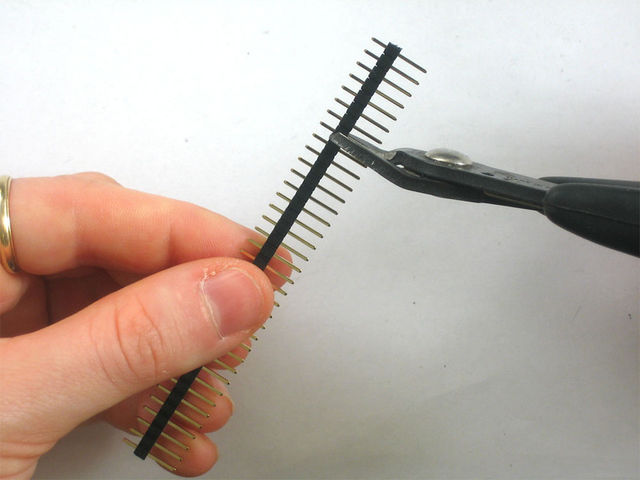
Crédit: AdaFruit Industries www.adafruit.com
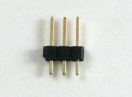
Crédit: AdaFruit Industries www.adafruit.com
Solder the two small pieces to the SEL0 and SEL1 pads. These are interface selectors for the chip. Depending on how the jumpers are inserted the chip will talk in TTL serial, i2c or SPI. Also solder a strip to the end so you can plug it into a breadboard.
Crédit: AdaFruit Industries www.adafruit.com
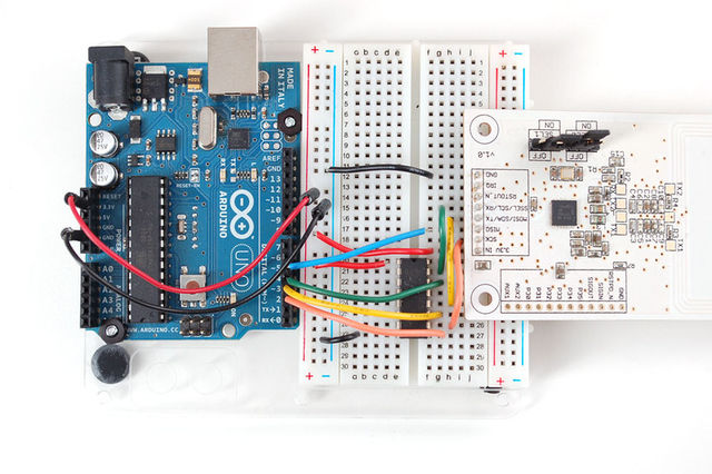
Wire up the 4050 level shifter chip to the Arduino as shown. The notch in the 4050 is at the 'top' in this image.
- Arduino digital pin 2 is connected to 4050 pin 9 (orange wire)
- Arduino digital pin 3 is connected to 4050 pin 11(yellow wire)
- Arduino digital pin 4 is connected to 4050 pin 14 (green wire)
Suggestion: Vous pourriez également utiliser un convertisseur de niveau logique 4 bit comme celui-ci.
On the breakout board
- 3.3Vin is connected to the Arduino 3.3V pn
- SCK is connected to 4050 pin 10 (orange wire)
- MISO is connected to Arduino pin 5 (blue wire)
- MOSI is connected to 4050 pin 12 (yellow wire)
- SSEL is connected to 4050 pin 15& (green wire)
- GND connects to Arduino ground (black wire)
Also connect 4050 pin #1 to 3.3V and pin #8 to ground.
Click to see a larger image. The red power wire should be connected to the 3.3v pin on the Arduino!
Crédit: AdaFruit Industries www.adafruit.com
Also, we need to select SPI as the interface so on SEL1 place the jumper in the ON position. for SEL0 place the jumper in the OFF position.
That's it! Later on you can change what Arduino pins you are using but for the beginning test we suggest matching our wiring.
Utilisation en I2C
| If you are using the shield in I2C mode, you will also need to add two 1.5K pullups on the SCL/SDA lines, since the breakout and the Arduino don't include the pullups. Simply solder or add a 1.5K resistor between SCL and 3.3V, and SDA and 3.3V, and then connect the breakout as you normally would. |
Source: PN532 RFID/NFC Breakout and Shield créé par LadyAda pour AdaFruit Industries. Crédit [www.adafruit.com AdaFruit Industries]
Traduit par Meurisse D. pour MCHobby.be
Traduit avec l'autorisation d'AdaFruit Industries - Translated with the permission from Adafruit Industries - www.adafruit.com
Toute référence, mention ou extrait de cette traduction doit être explicitement accompagné du texte suivant : « Traduction par MCHobby (www.MCHobby.be) - Vente de kit et composants » avec un lien vers la source (donc cette page) et ce quelque soit le média utilisé.
L'utilisation commercial de la traduction (texte) et/ou réalisation, même partielle, pourrait être soumis à redevance. Dans tous les cas de figures, vous devez également obtenir l'accord du(des) détenteur initial des droits. Celui de MC Hobby s'arrêtant au travail de traduction proprement dit.