Différences entre versions de « Pololu-Romi-Chassis-Assembler »
| Ligne 21 : | Ligne 21 : | ||
== Moteurs == | == Moteurs == | ||
| − | + | 1. Align the motor clips with the chassis as indicated and press them firmly into the chassis until the bottom of the clips are even with the bottom of the chassis (you may hear several clicks). | |
{{POLImage|Pololu-Romi-Chassis-Assembler-10.png|800px|Installer les clips moteurs sur le châssis Romi}} | {{POLImage|Pololu-Romi-Chassis-Assembler-10.png|800px|Installer les clips moteurs sur le châssis Romi}} | ||
| − | + | 2. '''Optional:''' If you are using the {{pl|1452|Romi Encoder Pair Kit}} {{polpl|3542}}, you can now install the encoder boards. The encoder boards are designed to be soldered directly to the back of the motor, with the back shaft of the motor protruding through the hole in the middle of the circuit board. One way to achieve good alignment between the board and the motor is to tack down the board to one motor pin and to solder the other pin only when the board is flat and well aligned. Be careful to avoid prolonged heating of the motor pins, which could deform the motor case or brushes. If you are using one of our boards that are designed for these encoders to plug directly into, the encoder pins need to be installed pointing down toward the chassis as shown in the picture below. In order to help line up the header pins before soldering them, you can hold off soldering them to the encoder board until after the motors are installed in the next step. | |
{{POLImage|Pololu-Romi-Chassis-Assembler-11.png|500px|Installer un encodeur sur le mini moteur plastique}} | {{POLImage|Pololu-Romi-Chassis-Assembler-11.png|500px|Installer un encodeur sur le mini moteur plastique}} | ||
| − | Push the Mini Plastic Gearmotors into the motor clips until they snap into place. Note that the motor blocks the clip release, so if you need to remove a motor bracket later, you will first need to remove the motor. The Mini Plastic Gearmotors that come with the kit have extended motor shafts to enable quadrature encoders (not included) for position feedback. | + | 3. Push the Mini Plastic Gearmotors into the motor clips until they snap into place. Note that the motor blocks the clip release, so if you need to remove a motor bracket later, you will first need to remove the motor. The Mini Plastic Gearmotors that come with the kit have extended motor shafts to enable quadrature encoders (not included) for position feedback. |
| − | {{POLImage|Pololu-Romi-Chassis-Assembler-12.png| | + | {{POLImage|Pololu-Romi-Chassis-Assembler-12.png|800px|Installer les moteurs sur le châssis}} |
== Les roues et la boule == | == Les roues et la boule == | ||
Version du 20 mars 2019 à 23:48
|
|
En cours de traduction/élaboration. |
En vidéo
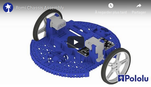
Cette vidéo de Pololu (YouTube) montre une animation de l'assemblage de la plateforme Romi.
Contact de pile et électonique
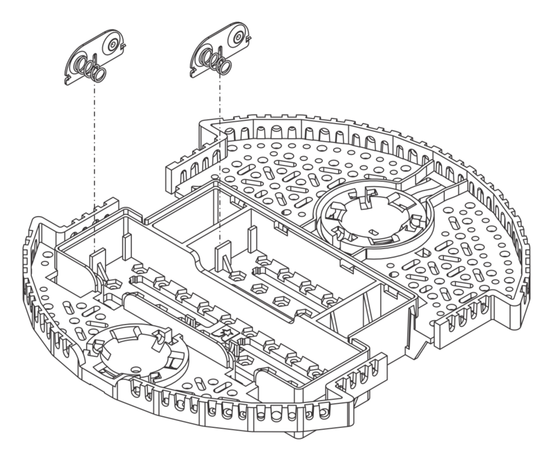
- With the chassis upside down, push the two double-sided battery contacts in the slots indicated in the picture below.
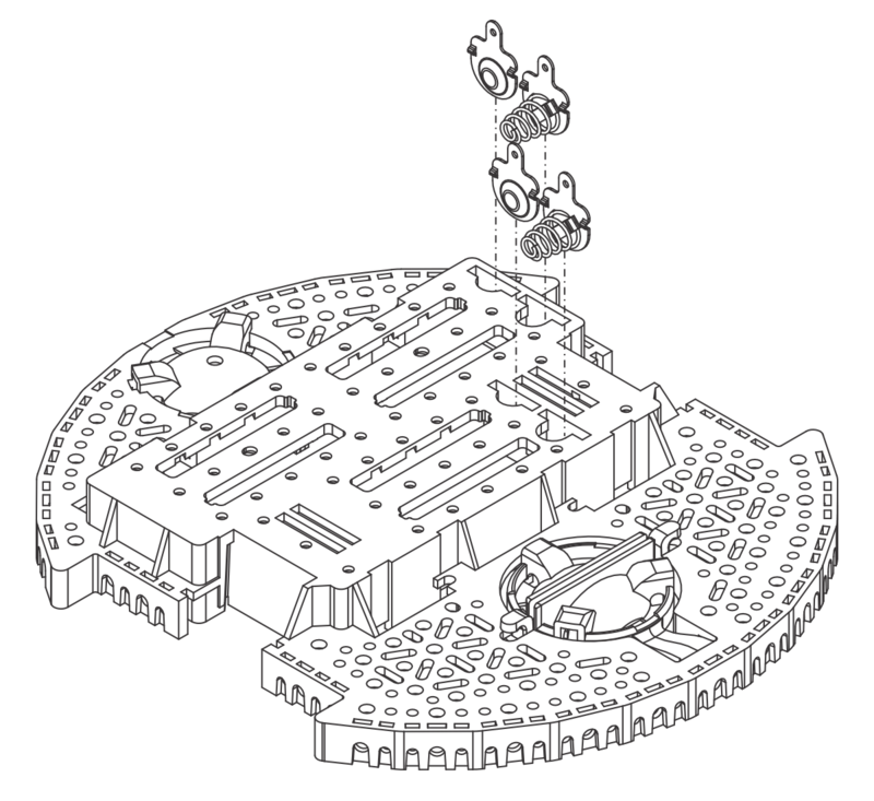
- Turn the chassis over and place the four individual battery contact terminals into the chassis from the top side of the battery box. They should rest loosely in their slots when the chassis is upright.
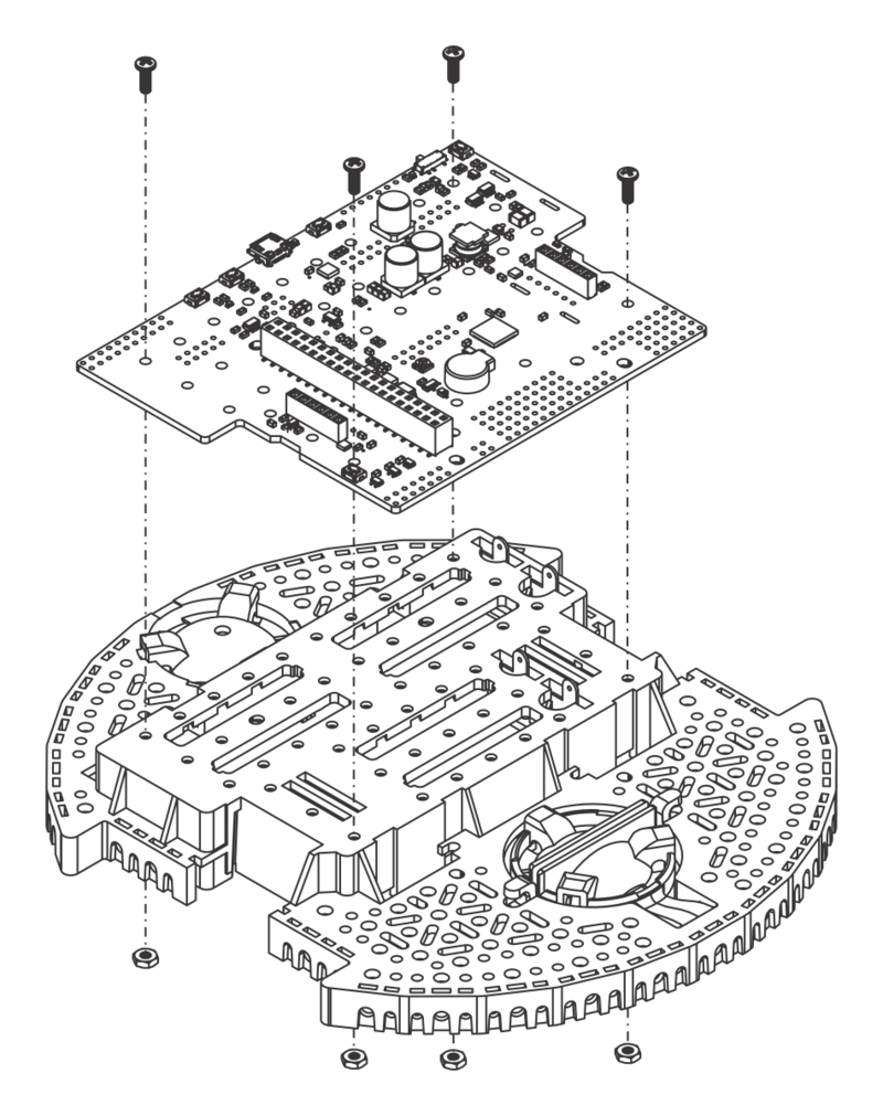
- Optional: If you have electronics that solder to the battery contacts, this is a convenient time to install them. The carte de contrôle Romi 32U4 lien pololu (not included) is shown below as an example.
Moteurs
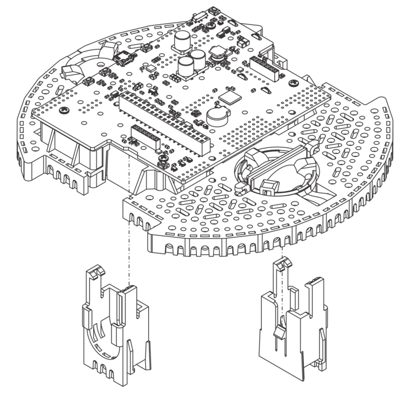
1. Align the motor clips with the chassis as indicated and press them firmly into the chassis until the bottom of the clips are even with the bottom of the chassis (you may hear several clicks).
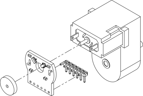
2. Optional: If you are using the Romi Encoder Pair Kit lien pololu, you can now install the encoder boards. The encoder boards are designed to be soldered directly to the back of the motor, with the back shaft of the motor protruding through the hole in the middle of the circuit board. One way to achieve good alignment between the board and the motor is to tack down the board to one motor pin and to solder the other pin only when the board is flat and well aligned. Be careful to avoid prolonged heating of the motor pins, which could deform the motor case or brushes. If you are using one of our boards that are designed for these encoders to plug directly into, the encoder pins need to be installed pointing down toward the chassis as shown in the picture below. In order to help line up the header pins before soldering them, you can hold off soldering them to the encoder board until after the motors are installed in the next step.
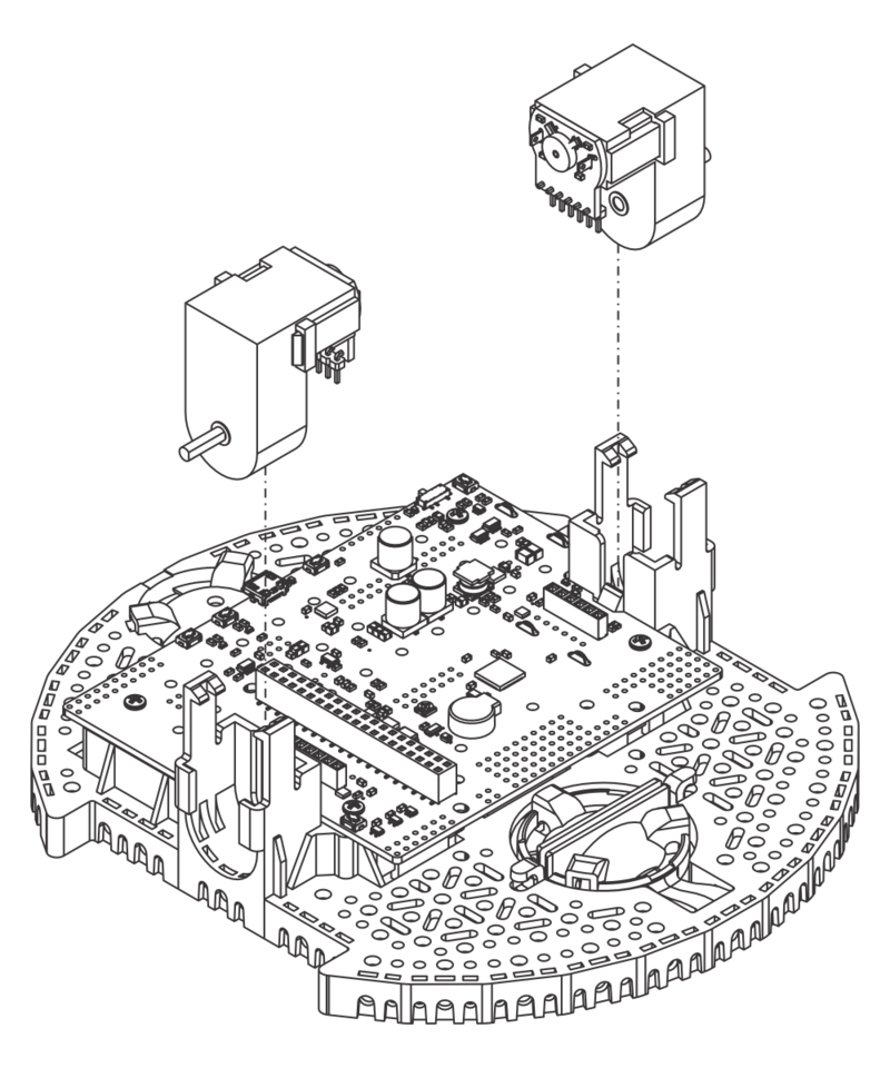
3. Push the Mini Plastic Gearmotors into the motor clips until they snap into place. Note that the motor blocks the clip release, so if you need to remove a motor bracket later, you will first need to remove the motor. The Mini Plastic Gearmotors that come with the kit have extended motor shafts to enable quadrature encoders (not included) for position feedback.
Les roues et la boule
xxx
Basé sur "Romi Chassis User’s Guide" de Pololu (https://www.pololu.com/docs/0J68) - Traduit en Français par shop.mchobby.be CC-BY-SA pour la traduction
Toute copie doit contenir ce crédit, lien vers cette page et la section "crédit de traduction". Traduit avec l'autorisation expresse de Pololu (www.pololu.com)
Based on "Romi Chassis User’s Guide" from Pololu (https://www.pololu.com/docs/0J68) - Translated to French by shop.mchobby.be CC-BY-SA for the translation
Copies must includes this credit, link to this page and the section "crédit de traduction" (translation credit). Translated with the Pololu's authorization (www.pololu.com)
