Différences entre versions de « Pololu-Zumo-Shield-Arduino-RC-Zumo »
| Ligne 9 : | Ligne 9 : | ||
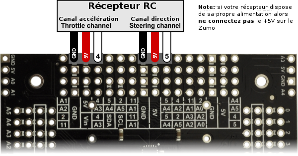
An easy way to connect the receiver to the Zumo Shield is to solder two 1×3 male header strips {{polpl|966}} to the locations shown in the diagram below, then plug in a pair of standard servo cables <small>[https://www.pololu.com/category/112/servo-cables lien pololu]</small>between the receiver and the Zumo Shield. (If your receiver has a separate power source, you should only connect the signal and ground wires between it and the Zumo.) | An easy way to connect the receiver to the Zumo Shield is to solder two 1×3 male header strips {{polpl|966}} to the locations shown in the diagram below, then plug in a pair of standard servo cables <small>[https://www.pololu.com/category/112/servo-cables lien pololu]</small>between the receiver and the Zumo Shield. (If your receiver has a separate power source, you should only connect the signal and ground wires between it and the Zumo.) | ||
| − | {POLImage|Pololu-Zumo-Shield-Arduino-RC-Zumo-01.png|600px|Diagramme de connexion du récepteur RC sur le shield Zumo.}} | + | {{POLImage|Pololu-Zumo-Shield-Arduino-RC-Zumo-01.png|600px|Diagramme de connexion du récepteur RC sur le shield Zumo.}} |
This program uses Arduino’s [http://arduino.cc/en/Reference/PulseIn PulseIn library] to read the signals from the receiver. By default, it assumes the throttle and steering channels are connected as the diagram shows on pins 4 and 5, respectively. The signals from the two channels are mixed to determine the left and right motor speeds, allowing for more intuitive control. | This program uses Arduino’s [http://arduino.cc/en/Reference/PulseIn PulseIn library] to read the signals from the receiver. By default, it assumes the throttle and steering channels are connected as the diagram shows on pins 4 and 5, respectively. The signals from the two channels are mixed to determine the left and right motor speeds, allowing for more intuitive control. | ||
| − | + | {{Pololu-Zumo-Shield-Arduino-TRAILER}} | |
Version du 12 avril 2017 à 20:19
|
|
En cours de traduction/élaboration. |
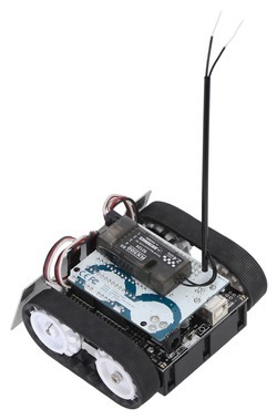
By connecting an RC receiver and running this example program, you can turn your Zumo into a radio-controlled vehicle. With the Zumo Shield Arduino Libraries installed, the sketch file can be opened in Arduino by selecting File > Examples > ZumoExamples > RCControl.
An easy way to connect the receiver to the Zumo Shield is to solder two 1×3 male header strips lien pololu to the locations shown in the diagram below, then plug in a pair of standard servo cables lien pololubetween the receiver and the Zumo Shield. (If your receiver has a separate power source, you should only connect the signal and ground wires between it and the Zumo.)
This program uses Arduino’s PulseIn library to read the signals from the receiver. By default, it assumes the throttle and steering channels are connected as the diagram shows on pins 4 and 5, respectively. The signals from the two channels are mixed to determine the left and right motor speeds, allowing for more intuitive control.
Basé sur "Zumo Shield for Arduino" de Pololu (www.pololu.com/docs/0J57) - Traduit en Français par shop.mchobby.be CC-BY-SA pour la traduction
Toute copie doit contenir ce crédit, lien vers cette page et la section "crédit de traduction". Traduit avec l'autorisation expresse de Pololu (www.pololu.com)
Based on "Zumo Shield for Arduino" from Pololu (www.pololu.com/docs/0J57) - Translated to French by shop.mchobby.be CC-BY-SA for the translation
Copies must includes this credit, link to this page and the section "crédit de traduction" (translation credit). Translated with the Pololu's authorization (www.pololu.com)

