Différences entre versions de « Pololu-Zumo-Shield-Arduino-RC-Zumo »
| Ligne 10 : | Ligne 10 : | ||
Ce programme utilise la [http://arduino.cc/en/Reference/PulseIn bibliothèque PulseIn] d'Arduino pour lire le signal en provenance du récepteur. Par défault, l'exemple par du principe que les canaux accélérateur (''throttle'') et direction (''steering'') sont connecté respectivement sur les broches 4 et 5 (comme sur le diagramme). Le signal des deux canaux est analysé pour déterminer la vitesse du moteur droit et moteur gauche (ce qui permet un contrôle plus intuitif). | Ce programme utilise la [http://arduino.cc/en/Reference/PulseIn bibliothèque PulseIn] d'Arduino pour lire le signal en provenance du récepteur. Par défault, l'exemple par du principe que les canaux accélérateur (''throttle'') et direction (''steering'') sont connecté respectivement sur les broches 4 et 5 (comme sur le diagramme). Le signal des deux canaux est analysé pour déterminer la vitesse du moteur droit et moteur gauche (ce qui permet un contrôle plus intuitif). | ||
| + | |||
| + | == Code == | ||
| + | Voici une copie de l'exemple avec traduction des commentaires pour vous aider à mieux comprendre le fonctionnement du croquis/sketch | ||
| + | |||
| + | <syntaxhighlight lang="c"> | ||
| + | #include <ZumoMotors.h> | ||
| + | |||
| + | #define THROTTLE_PIN 4 // throttle channel from RC receiver | ||
| + | #define STEERING_PIN 5 // steering channel from RC receiver | ||
| + | #define LED_PIN 13 // user LED pin | ||
| + | |||
| + | #define MAX_SPEED 400 // max motor speed | ||
| + | #define PULSE_WIDTH_DEADBAND 25 // pulse width difference from 1500 us (microseconds) to ignore (to compensate for control centering offset) | ||
| + | #define PULSE_WIDTH_RANGE 350 // pulse width difference from 1500 us to be treated as full scale input (for example, a value of 350 means | ||
| + | // any pulse width <= 1150 us or >= 1850 us is considered full scale) | ||
| + | |||
| + | |||
| + | void setup() | ||
| + | { | ||
| + | pinMode(LED_PIN, OUTPUT); | ||
| + | |||
| + | // uncomment one or both of the following lines if your motors' directions need to be flipped | ||
| + | //motors.flipLeftMotor(true); | ||
| + | //motors.flipRightMotor(true); | ||
| + | } | ||
| + | |||
| + | void loop() | ||
| + | { | ||
| + | int throttle = pulseIn(THROTTLE_PIN, HIGH); | ||
| + | int steering = pulseIn(STEERING_PIN, HIGH); | ||
| + | |||
| + | int left_speed, right_speed; | ||
| + | |||
| + | if (throttle > 0 && steering > 0) | ||
| + | { | ||
| + | // both RC signals are good; turn on LED | ||
| + | digitalWrite(LED_PIN, HIGH); | ||
| + | |||
| + | // RC signals encode information in pulse width centered on 1500 us (microseconds); subtract 1500 to get a value centered on 0 | ||
| + | throttle -= 1500; | ||
| + | steering -= 1500; | ||
| + | |||
| + | // apply deadband | ||
| + | if (abs(throttle) <= PULSE_WIDTH_DEADBAND) | ||
| + | throttle = 0; | ||
| + | if (abs(steering) <= PULSE_WIDTH_DEADBAND) | ||
| + | steering = 0; | ||
| + | |||
| + | // mix throttle and steering inputs to obtain left & right motor speeds | ||
| + | left_speed = ((long)throttle * MAX_SPEED / PULSE_WIDTH_RANGE) - ((long)steering * MAX_SPEED / PULSE_WIDTH_RANGE); | ||
| + | right_speed = ((long)throttle * MAX_SPEED / PULSE_WIDTH_RANGE) + ((long)steering * MAX_SPEED / PULSE_WIDTH_RANGE); | ||
| + | |||
| + | // cap speeds to max | ||
| + | left_speed = min(max(left_speed, -MAX_SPEED), MAX_SPEED); | ||
| + | right_speed = min(max(right_speed, -MAX_SPEED), MAX_SPEED); | ||
| + | } | ||
| + | else | ||
| + | { | ||
| + | // at least one RC signal is not good; turn off LED and stop motors | ||
| + | digitalWrite(LED_PIN, LOW); | ||
| + | |||
| + | left_speed = 0; | ||
| + | right_speed = 0; | ||
| + | } | ||
| + | |||
| + | ZumoMotors::setSpeeds(left_speed, right_speed); | ||
| + | } | ||
| + | </syntaxhighlight> | ||
{{Pololu-Zumo-Shield-Arduino-TRAILER}} | {{Pololu-Zumo-Shield-Arduino-TRAILER}} | ||
Version du 17 avril 2017 à 18:28
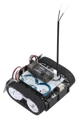
En connectant un récepteur RC (Radio Commande) et en exécutant ce programme d'exemple, vous pouvez transformer un Zumo en véhicule télécommandé. Si vous avez installé la bibliothèque Shield Zumo pour Arduino alors vous trouverez le croquis/sketch Arduino via le point de menu Fichier > Exemples > ZumoExamples > RCControl.
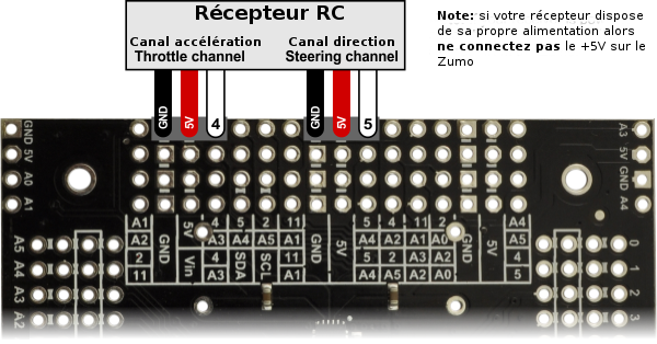
Pour connecter facilement un récepteur sur le Shield Zumo, vous pouvez souder deux connecteur/pinHeader mâle 1×3 broches lien pololu comme indiqué sur le diagramme ci-dessous. Ensuite, vous pouvez connecter une paire de câble servo lien pololu entre le récepteur et les shield Zumo. (Si votre récepteur RC dispose d'une source d'alimentation séparée alors vous devriez uniquement connecter la masse et le source du signal vers votre Zumo.)
Ce programme utilise la bibliothèque PulseIn d'Arduino pour lire le signal en provenance du récepteur. Par défault, l'exemple par du principe que les canaux accélérateur (throttle) et direction (steering) sont connecté respectivement sur les broches 4 et 5 (comme sur le diagramme). Le signal des deux canaux est analysé pour déterminer la vitesse du moteur droit et moteur gauche (ce qui permet un contrôle plus intuitif).
Code
Voici une copie de l'exemple avec traduction des commentaires pour vous aider à mieux comprendre le fonctionnement du croquis/sketch
#include <ZumoMotors.h>

#define THROTTLE_PIN   4 // throttle channel from RC receiver
#define STEERING_PIN   5 // steering channel from RC receiver
#define LED_PIN       13 // user LED pin

#define MAX_SPEED             400 // max motor speed
#define PULSE_WIDTH_DEADBAND   25 // pulse width difference from 1500 us (microseconds) to ignore (to compensate for control centering offset)
#define PULSE_WIDTH_RANGE     350 // pulse width difference from 1500 us to be treated as full scale input (for example, a value of 350 means
                                  //   any pulse width <= 1150 us or >= 1850 us is considered full scale)


void setup()
{
  pinMode(LED_PIN, OUTPUT);

  // uncomment one or both of the following lines if your motors' directions need to be flipped
  //motors.flipLeftMotor(true);
  //motors.flipRightMotor(true);
}

void loop()
{
  int throttle = pulseIn(THROTTLE_PIN, HIGH);
  int steering = pulseIn(STEERING_PIN, HIGH);

  int left_speed, right_speed;

  if (throttle > 0 && steering > 0)
  {
    // both RC signals are good; turn on LED
    digitalWrite(LED_PIN, HIGH);

    // RC signals encode information in pulse width centered on 1500 us (microseconds); subtract 1500 to get a value centered on 0
    throttle -= 1500;
    steering -= 1500;

    // apply deadband
    if (abs(throttle) <= PULSE_WIDTH_DEADBAND)
      throttle = 0;
    if (abs(steering) <= PULSE_WIDTH_DEADBAND)
      steering = 0;

    // mix throttle and steering inputs to obtain left & right motor speeds
    left_speed = ((long)throttle * MAX_SPEED / PULSE_WIDTH_RANGE) - ((long)steering * MAX_SPEED / PULSE_WIDTH_RANGE);
    right_speed = ((long)throttle * MAX_SPEED / PULSE_WIDTH_RANGE) + ((long)steering * MAX_SPEED / PULSE_WIDTH_RANGE);

    // cap speeds to max
    left_speed = min(max(left_speed, -MAX_SPEED), MAX_SPEED);
    right_speed = min(max(right_speed, -MAX_SPEED), MAX_SPEED);
  }
  else
  {
    // at least one RC signal is not good; turn off LED and stop motors
    digitalWrite(LED_PIN, LOW);

    left_speed = 0;
    right_speed = 0;
  }

  ZumoMotors::setSpeeds(left_speed, right_speed);
}
Basé sur "Zumo Shield for Arduino" de Pololu (www.pololu.com/docs/0J57) - Traduit en Français par shop.mchobby.be CC-BY-SA pour la traduction
Toute copie doit contenir ce crédit, lien vers cette page et la section "crédit de traduction". Traduit avec l'autorisation expresse de Pololu (www.pololu.com)
Based on "Zumo Shield for Arduino" from Pololu (www.pololu.com/docs/0J57) - Translated to French by shop.mchobby.be CC-BY-SA for the translation
Copies must includes this credit, link to this page and the section "crédit de traduction" (translation credit). Translated with the Pololu's authorization (www.pololu.com)

