Différences entre versions de « Pololu-Zumo-Shield-Arduino-assembler-shield »
| Ligne 28 : | Ligne 28 : | ||
On the bottom of the board, trim the four Arduino header pins closest to the front of the board on each side to prevent them from contacting the motor housings. If you think there is a chance these pins might still touch the motor cases, you can put some electrical tape on the motors to act as insulation. | On the bottom of the board, trim the four Arduino header pins closest to the front of the board on each side to prevent them from contacting the motor housings. If you think there is a chance these pins might still touch the motor cases, you can put some electrical tape on the motors to act as insulation. | ||
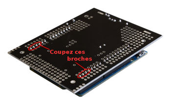
| − | {{POLImage|Pololu-Zumo-Shield-Arduino-assembler-shield-11.jpg|350px|Le Zumo Shield | + | {{POLImage|Pololu-Zumo-Shield-Arduino-assembler-shield-11.jpg|350px|Le Zumo Shield soudé et connecteurs Arduino coupé}} |
== Cavaliers et connexions complémentaires== | == Cavaliers et connexions complémentaires== | ||
Version du 7 avril 2017 à 14:39
|
|
En cours de traduction/élaboration. |
Please follow these instructions carefully to assemble your Zumo Shield and chassis properly. (These pictures show the original Zumo Shield lien pololu , but the assembly process is the same for the latest v1.2 version lien pololu )
Les composants traversants
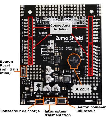
- Solder the included through-hole components to the shield:
- power switch
- reset pushbutton
- user pushbutton
- buzzer
- charging connector (1×2-pin female header)
- On the bottom of the board, trim any leads longer than 1/16″ (the thickness of the spacer plate) so they do not prevent the shield from sitting flat on the spacer plate and chassis.
Connecteurs Arduino
Separate the 1×40-pin breakaway male header into the appropriate segments for connecting your Arduino and solder them to the shield. These header segments should be soldered to the sets of holes outlined with white rectangles on the top of the shield, with the pins facing up.
The A-Star 32U4 Primes and the newest Arduino boards, including the Uno R3 and the Leonardo, use one 1×10 header, two 1×8 headers, and one 1×6 header; older Arduino boards use two 1×8 headers and two 1×6 headers (the two pairs of pins highlighted above in red should not be populated if you are using this board with an older Arduino that does not support these additional pins). Please make sure you solder the appropriate headers for your particular Arduino!
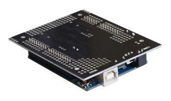
An easy way to line up the Arduino headers for soldering is to plug them into an Arduino, then place the shield upside-down on top of them, as shown in the picture below. Be careful to insert the header pins into the correct set of holes before you begin soldering. Note: if you use this alignment technique, make sure your soldering iron temperature is not excessively hot and avoid holding the iron on a single pin for more than a few seconds as this could melt the Arduino’s female headers.
On the bottom of the board, trim the four Arduino header pins closest to the front of the board on each side to prevent them from contacting the motor housings. If you think there is a chance these pins might still touch the motor cases, you can put some electrical tape on the motors to act as insulation.
Cavaliers et connexions complémentaires
Optional: If you want to enable the buzzer, enable the battery level input, or disable the compass, now is a good time to add and/or cut jumper connections to configure the shield to your liking. This can also be done later, though soldering to these pins is more difficult once the robot is assembled (especially if you decide later you want to add header pins for use with shorting blocks; this would require a lot of disassembly). The jumpers are explained in detail in Section 3.c. The buzzer and battery level jumpers can be connected by soldering in a short piece of wire between the two holes, while the compass I²C connections can be broken by cutting the trace on the top of the board between the holes.
Note: there is not enough clearance to use male headers on the battery level and compass I²C jumpers if you are using an Arduino with a DIP (through-hole) microcontroller.
Basé sur "Zumo Shield for Arduino" de Pololu (www.pololu.com/docs/0J57) - Traduit en Français par shop.mchobby.be CC-BY-SA pour la traduction
Toute copie doit contenir ce crédit, lien vers cette page et la section "crédit de traduction". Traduit avec l'autorisation expresse de Pololu (www.pololu.com)
Based on "Zumo Shield for Arduino" from Pololu (www.pololu.com/docs/0J57) - Translated to French by shop.mchobby.be CC-BY-SA for the translation
Copies must includes this credit, link to this page and the section "crédit de traduction" (translation credit). Translated with the Pololu's authorization (www.pololu.com)


