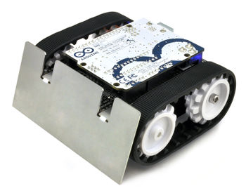
Pololu-Zumo-Shield-Arduino-assembler-shield
|
|
En cours de traduction/élaboration. |
Introduction
Suivez soigneusement ces instructions pour assembler correctement le Shield Zumo et le châssis. (Ces images présente le shield Zumo original lien pololu mais les étapes d'assemblage restent identique pour la dernière version v1.2 lien pololu )
Les composants traversants
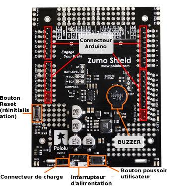
- Soudez les composants traversant sur le shield:
- Interrupteur d'alimentation (dit power en anglais)
- Le bouton poussoir "reset" (réinitialisation de la carte Arduino)
- Le bouton utilisateur (dit user en anglais)
- Le buzzer
- Le connecteur de charge (connecteur femelle 1×2-broches)
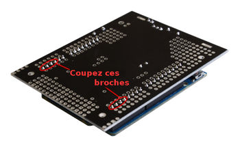
- En dessous de la carte, coupez les broches qui dépassent de plus 1.5mm (l'épaisseur de la plaque entretoise) afin que les broches n'empêche pas le shield de prendre sa position BIEN A PLAT sur le châssis et la plaque entretoise.
Connecteurs Arduino
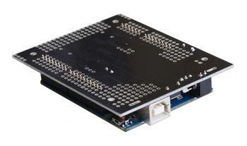
Brisez le connecteur mâle/pinHeader 1×40-broches en segments pour connecter votre Arduino et les souders sur le shield. Placez ces connecteurs sur votre carte Arduino puis venez placer le shield par dessus. la partie courte des connecteurs doivent dépasser par les trous du shield.
Faites bien attention à positionner le shield et l'Arduino comme indiqué sur l'image.
L' A-Star 32U4 Primes et le nouvel Arduino (Arduino R3 et Leonardo) utilisent un connecteur 1×10 broches, deux connecteur 1×8 broches et un connecteur 1×6 broches; les cartes Arduino plus anciennes utilisent deux connecteur 1×8 et deux connecteur 1×6 (les deux paires de broches mises en surbrillance ci-dessous ne doivent pas être peuplés si vous utilisez une ancienne carte Arduino qui ne supportait par encore les nouvelles broches de la révision R3). Faites attention à bien souder le nombre de broches correspondant à votre révision d'Arduino!
Une façon simple et efficace d'aligner les connecteur sur le shield est d'utiliser votre Arduino. Vous y enfoncez la partie longue des pinHeader/connecteur mâle dans les connecteurs de votre Arduino, puis vous placez le shield (face vers le bas) comme montré sur l'image. Faites attention à bien insérer les têtes des broches dans les bons trous du shield avant de commencer à souder. Note: si vous utilisez cette technique, assurez vous que votre fer à souder ne soit pas trop chaud (de façon excessive) et évitez de maintenir le fer en contact avec la broches plus de quelques secondes.... sinon vous risquez de fondre le connecteur femelle de votre Arduino.
En dessous de la carte: coupez les connecteurs Arduino au ras de la carte (aussi proche que possible du shield) de sorte qu'elles ne rentrent pas en contact avec la carcasse du moteur. Si vous craignez que la broche rentre malgré tout en contact avec la carcasse des moteurs, vous pouvez utilisez de la toile isolante comme isolant.
Cavaliers et connexions complémentaires
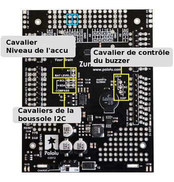
- Optional: If you want to enable the buzzer, enable the battery level input, or disable the compass, now is a good time to add and/or cut jumper connections to configure the shield to your liking. This can also be done later, though soldering to these pins is more difficult once the robot is assembled (especially if you decide later you want to add header pins for use with shorting blocks; this would require a lot of disassembly). The jumpers are explained in detail in Section 3.c. The buzzer and battery level jumpers can be connected by soldering in a short piece of wire between the two holes, while the compass I²C connections can be broken by cutting the trace on the top of the board between the holes.
Note: there is not enough clearance to use male headers on the battery level and compass I²C jumpers if you are using an Arduino with a DIP (through-hole) microcontroller.
| Instead of making a wire connection, you can solder a 1×3 male header to the buzzer jumper holes to allow the use of a shorting block for connecting the buzzer. You can also use male headers and shorting blocks for the battery level jumper and compass jumpers if you have an Arduino Uno with an SMD (surface mount) microcontroller, Arduino Leonardo, or A-Star 32U4 Prime. However, there is not enough clearance to use male headers on the battery level and compass I²C jumpers if you are using an Arduino with a DIP (through-hole) microcontroller. |
- Optional: At this point, you might consider soldering additional components (such as sensors), or headers or wires for connecting them, to the shield. If you do this, please check to make sure your part placement does not interfere with the shield’s ability to mate with the Arduino or the chassis. In particular, note that only components in the outermost three rows of the front expansion area can extend below the board (the fourth front-expansion row can only be used for pins extending above the board), and if you add any through-hole parts to the prototyping areas on the shield, you will need to drill corresponding holes in the acrylic spacer plate for the leads to fit into.
Les moteurs
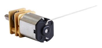
- Cut two of the included jumper wires in half to form four segments, and trim off the ends that are covered in adhesive (the adhesive could interfere with making a good electrical connection to the motor). These wire segments will be used as motor leads.
- Solder a pair of leads to each motor. You might find it helpful to make a small bend at the tip of each lead to hook into the hole in the motor lead tab to hold it in place for soldering. Warning: holding the soldering iron against the motor lead for more than a few seconds can start to damage the motor brushes, so try to be reasonably quick/efficient with this soldering; if the first attempt does not go well, remove the soldering iron and let the motor cool for a few seconds before trying again.
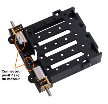
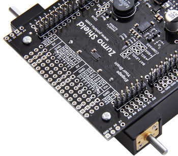
Each motor’s positive terminal is indicated by a plus sign (+) in the black plastic end of the motor, visible at the bottom of the picture above. The motors should be soldered into the shield with the positive terminal closest to the front, so you should attach the leads to allow the motors to be oriented this way. (However, don’t worry if you accidentally get the orientation of one or both motors wrong. You can later compensate for it in software with our ZumoMotors library.)
- Place the motors into the channel in the front of the chassis, aligning the gearbox with the grooves in the channel. The front plate of the gearbox should be even with the edge of the chassis.
Châssis et shield
| To assemble the chassis with the Zumo Shield, you should use the two-piece acrylic spacer plate that is included with the shield. You will not need the one-piece mounting plate that is included with the Zumo chassis. |
- Place an M3 nut in each of the two side slots near the rear of the chassis. The slots are sized so that nuts will not be able to rotate within them. (These nuts will be used to mount the idler sprockets later.)
- If you want, peel the protective paper masking off both sides of the acrylic spacer plate pieces (the spacer plates in our pictures show what they will look like with the masking peeled off). Alternatively, you can leave the masking on for additional thickness. If you leave the masking on, it will be mostly concealed when the robot is fully assembled.
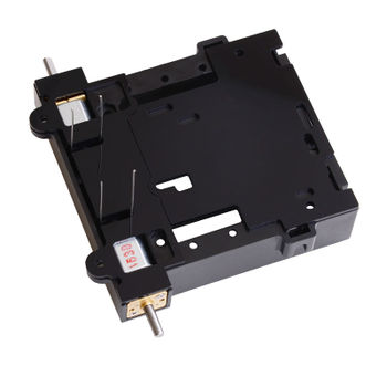
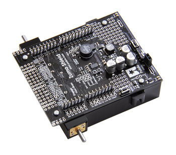
- Cover the chassis and motors with the spacer plate pieces and then the Zumo shield. The holes in the spacer plate should line up with the through-holes in the shield resting on top of it, and the motor leads should be aligned so they pass through the slots in the spacer as shown in the picture below. There is only one correct orientation for these plates. (The plate consists of two separate pieces to make it possible to disassemble the Zumo without having to desolder the motors or battery terminals.)
- In each of the four mounting holes, insert a #2-56 machine screw through the shield, spacer plate, and chassis, and tighten it against a nut under the chassis. It is usually easier to place the nut into the recess first and hold it there with a finger or piece of tape while inserting the screw. Note that the kit includes two different sizes of #2-56 machine screws: 1/4″and 5/16″. The two longer screws are intended for use in the front holes (near the motors) if you are also mounting a sumo blade; otherwise, you can use the shorter 1/4″ screws for all four mounting holes.
If you are also adding a basic sumo blade, you can either mount it now or add it later after you are done soldering the motors and battery contacts. (Note: If you intend to solder anything to the front expansion area of the shield, such as a Zumo reflectance sensor array, you will have more room to work if you do the soldering before adding the sumo blade.)
| There is a small chance the mounting tabs of the blade can cause shorts where it contacts the shield if the PCB solder mask is not thick enough, so we recommend adding some electrical tape or other insulating material between the blade and shield. |
To install the blade, first bend its mounting tabs to the appropriate angle. Next, place them on top of the shield so that the holes line up with the two front mounting holes and insert the two longer (5/16″) #2-56 machine screws (included with the shield) through the blade, shield, spacer plate, and chassis. Be careful when adjusting the angle of the sumo blade while it is mounted to the chassis, as this can crack the acrylic spacer plate if you apply sudden or excessive force. We recommend you do not try bending the blade while it is mounted to the chassis.
- Solder each motor lead to the shield, then trim off the excess length of wire.
Contacts des piles
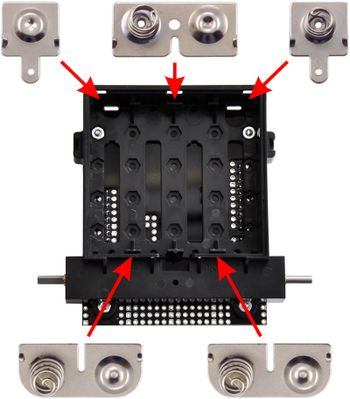
- Turn the chassis over and install the battery terminal contacts as shown in the picture below. The three double-contact pieces should be firmly pressed into place until they are flush with the interior surface of the battery compartment. The two individual contacts should be inserted into the battery compartment so that their solder tabs protrude through the holes in the top of the chassis; you might want to temporarily tape these two individual contacts in place until they have been soldered to the shield as described in the next step, or you can use a battery to temporarily hold them in place.
- Solder the two individual contacts to the shield from the top. Note that if you are using a battery to hold the contact in place during soldering, the battery might act as a heat sink, making it more difficult to solder or requiring a higher soldering iron temperature. The battery terminal slot in the PCB should be completely filled with solder as shown in the picture below.
Roues dentées et les chenilles
- Place an idler sprocket (pignon) on each shoulder bolt, followed by a washer. The side of the sprocket with “teeth” should face the same direction as the threaded end of the bolt, so that the teeth end up pointing in towards the chassis.
- Insert the shoulder bolts through the side of the chassis into the nut. Use a 3 mm hex key (Allen wrench) to tighten the bolts until the washers are snug against the chassis. Be careful not to overtighten the shoulder bolts as doing so can bend the washers. Note: Be careful if you use threadlocking adhesives like Loctite as these can corrode the chassis. You should first test any such adhesives on a concealed part of the chassis to ensure they will not damage it.
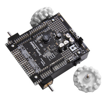
- Press the output shafts of the motors into the drive sprockets, with the “teeth” of the sprockets facing the motor. The end of the gearbox shaft should end up flush with the outside of the sprocket. A good way to accomplish this is to set the wheel on a table top and press the motor shaft into the wheel until it contacts the table.
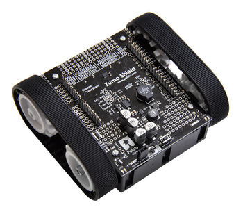
- At this point, you can add the silicone tracks by stretching them around the sprockets on each side of the chassis. Your Zumo Shield and chassis are now complete; just add batteries and an Arduino to get your Zumo robot moving!
Démonter
If you later decide you want to solder additional parts to the Zumo Shield, it is possible to remove it from the chassis with some careful effort.
- Remove the tracks from the chassis and carefully pull the drive sprockets off the motors.
- Remove the battery cover and batteries from the chassis.
- Unscrew all four sets of machine screws and nuts holding the shield to the chassis.
- Squeeze the negative battery terminal spring and gently ease both battery terminals out through the holes in the chassis. The motors will stay attached to the shield as it separates from the chassis.
- Carefully bend both motors away from the shield to allow the front piece of the spacer plate to be removed.
You can reassemble the Zumo afterwards by following this procedure in reverse. (Make sure to replace the spacer plate pieces properly.)
Basé sur "Zumo Shield for Arduino" de Pololu (www.pololu.com/docs/0J57) - Traduit en Français par shop.mchobby.be CC-BY-SA pour la traduction
Toute copie doit contenir ce crédit, lien vers cette page et la section "crédit de traduction". Traduit avec l'autorisation expresse de Pololu (www.pololu.com)
Based on "Zumo Shield for Arduino" from Pololu (www.pololu.com/docs/0J57) - Translated to French by shop.mchobby.be CC-BY-SA for the translation
Copies must includes this credit, link to this page and the section "crédit de traduction" (translation credit). Translated with the Pololu's authorization (www.pololu.com)
