Différences entre versions de « Pololu-Zumo-Shield-Arduino-fonctionnalites »
| Ligne 4 : | Ligne 4 : | ||
== Fonctionnalités principales == | == Fonctionnalités principales == | ||
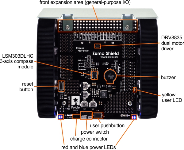
| + | The main features of the Zumo Shield (v1.2) are labeled in this diagram: | ||
| − | {{POLImage|Pololu-Zumo-Shield-Arduino-fonctionnalites-00.jpg| | + | {{POLImage|Pololu-Zumo-Shield-Arduino-fonctionnalites-00.jpg|744px|Zumo Shield, v1.2, vue du dessus avec identification des composants}} |
| + | |||
| + | For the original Zumo Shield, a corresponding [https://www.pololu.com/file/download/zumo-shield-v1.0-labeled-components.jpg?file_id=0J810 diagramme] (206k, jpg) is available (the only differences are the on-board inertial sensors). | ||
| + | |||
| + | == Alimentation == | ||
| + | The Zumo chassis has an internal compartment for four AA batteries. We recommend using rechargeable AA NiMH cells, which results in a nominal voltage of 4.8 V (1.2 V per cell). You can also use alkaline cells, which would nominally give you 6V. | ||
| + | |||
| + | A direct connection to the battery terminals is provided by the battery charger connector on the rear edge of the shield, which can be used to recharge the Zumo’s batteries without removing them from the chassis. The positive pin of the charge connector, on the left, is indicated by a plus sign (+). A charger like the iMAX-B6AC {{polpl|2588}}, connected by clipping its alligator clips to a pair of jumper wires inserted into the charge connector, works well for charging the Zumo. | ||
| + | |||
| + | After passing through reverse protection, the battery voltage is connected to the rest of the shield by the power switch. The switched battery voltage is designated VBAT and provides power to the motors through the DRV8835 motor driver. An on-board boost regulator, also supplied from VBAT, generates 7.45 V to power the Arduino through its Vin pin. In turn, the Arduino’s regulated 5V and 3.3V voltages supply power to the motor driver logic, buzzer circuit, and compass module on the Zumo Shield. | ||
| + | |||
| + | {{ambox-stop|text=Warning: When powering the Arduino from the Zumo Shield, you must never connect a different power supply to the Arduino’s VIN pin or plug a power supply into the Arduino’s power jack, as doing so will create a short between the shield’s power supply and the Arduino’s power supply that could permanently damage both the Arduino and the Zumo Shield.}} | ||
| + | |||
| + | {{ambox|text=When the Arduino is connected to a computer via USB, it will receive power (and supply 5V and 3.3V to the shield) even when the Zumo Shield’s power switch is off. This can be useful if you want to test your Arduino program without allowing the motors to run, since turning the power switch off disconnects motor power (VBAT).}} | ||
| + | |||
| + | == LEDs == | ||
| + | There are five LEDs on the Zumo Shield: | ||
| + | * A set of power LEDs, one <font color="blue">'''bleu'''</font> and one <font color="red">'''rouge'''</font>, is located in each of the two rear corners of the shield. | ||
| + | * A <font color="orange">'''jaune'''</font> user LED is located on the right edge of the shield. It is connected to '''digital pin 13''' on the Arduino, in parallel with the Arduino’s onboard user LED. | ||
| + | |||
| + | == Boutons poussoirs == | ||
| + | Two pushbuttons can be soldered to the Zumo Shield: | ||
| + | * The '''reset pushbutton''' is located on the left edge of the shield. It is connected to the Arduino’s RESET pin and can be pressed to reset the Arduino. | ||
| + | * The '''user pushbutton''' is located on the rear edge of the shield. It is connected to '''digital pin 12''' on the Arduino; pressing the button pulls the pin low, and we recommend enabling the Arduino’s internal pull-up to pull the pin high otherwise. The Pushbutton library, included with our Zumo Shield libraries, makes it easy to detect and debounce button presses with this pushbutton. | ||
{{Pololu-Zumo-Shield-Arduino-TRAILER}} | {{Pololu-Zumo-Shield-Arduino-TRAILER}} | ||
Version du 9 avril 2017 à 14:12
|
|
En cours de traduction/élaboration. |
Fonctionnalités principales
The main features of the Zumo Shield (v1.2) are labeled in this diagram:

For the original Zumo Shield, a corresponding diagramme (206k, jpg) is available (the only differences are the on-board inertial sensors).
Alimentation
The Zumo chassis has an internal compartment for four AA batteries. We recommend using rechargeable AA NiMH cells, which results in a nominal voltage of 4.8 V (1.2 V per cell). You can also use alkaline cells, which would nominally give you 6V.
A direct connection to the battery terminals is provided by the battery charger connector on the rear edge of the shield, which can be used to recharge the Zumo’s batteries without removing them from the chassis. The positive pin of the charge connector, on the left, is indicated by a plus sign (+). A charger like the iMAX-B6AC lien pololu, connected by clipping its alligator clips to a pair of jumper wires inserted into the charge connector, works well for charging the Zumo.
After passing through reverse protection, the battery voltage is connected to the rest of the shield by the power switch. The switched battery voltage is designated VBAT and provides power to the motors through the DRV8835 motor driver. An on-board boost regulator, also supplied from VBAT, generates 7.45 V to power the Arduino through its Vin pin. In turn, the Arduino’s regulated 5V and 3.3V voltages supply power to the motor driver logic, buzzer circuit, and compass module on the Zumo Shield.
| Warning: When powering the Arduino from the Zumo Shield, you must never connect a different power supply to the Arduino’s VIN pin or plug a power supply into the Arduino’s power jack, as doing so will create a short between the shield’s power supply and the Arduino’s power supply that could permanently damage both the Arduino and the Zumo Shield. |
| When the Arduino is connected to a computer via USB, it will receive power (and supply 5V and 3.3V to the shield) even when the Zumo Shield’s power switch is off. This can be useful if you want to test your Arduino program without allowing the motors to run, since turning the power switch off disconnects motor power (VBAT). |
LEDs
There are five LEDs on the Zumo Shield:
- A set of power LEDs, one bleu and one rouge, is located in each of the two rear corners of the shield.
- A jaune user LED is located on the right edge of the shield. It is connected to digital pin 13 on the Arduino, in parallel with the Arduino’s onboard user LED.
Boutons poussoirs
Two pushbuttons can be soldered to the Zumo Shield:
- The reset pushbutton is located on the left edge of the shield. It is connected to the Arduino’s RESET pin and can be pressed to reset the Arduino.
- The user pushbutton is located on the rear edge of the shield. It is connected to digital pin 12 on the Arduino; pressing the button pulls the pin low, and we recommend enabling the Arduino’s internal pull-up to pull the pin high otherwise. The Pushbutton library, included with our Zumo Shield libraries, makes it easy to detect and debounce button presses with this pushbutton.
Basé sur "Zumo Shield for Arduino" de Pololu (www.pololu.com/docs/0J57) - Traduit en Français par shop.mchobby.be CC-BY-SA pour la traduction
Toute copie doit contenir ce crédit, lien vers cette page et la section "crédit de traduction". Traduit avec l'autorisation expresse de Pololu (www.pololu.com)
Based on "Zumo Shield for Arduino" from Pololu (www.pololu.com/docs/0J57) - Translated to French by shop.mchobby.be CC-BY-SA for the translation
Copies must includes this credit, link to this page and the section "crédit de traduction" (translation credit). Translated with the Pololu's authorization (www.pololu.com)