Différences entre versions de « Pololu-Zumo-Shield-Arduino-fonctionnalites »
(→LEDs) |
|||
| Ligne 27 : | Ligne 27 : | ||
== Boutons poussoirs == | == Boutons poussoirs == | ||
| − | + | Deux boutons poussoirs peuvent être soudés sur le shield Zumo: | |
| − | * | + | * Le '''bouton Reset''' est localisé sur le bord gauche du shield. Il est connecté sur la broche RESET d'Arduino et peut être pressé pour réinitialiser votre Arduino. |
| − | * | + | * Le '''bouton Utilisateur''' (dit "''user''" en anglasi) est localisé sur la bordure arrière du shield. Le bouton est connecté sur la '''broche digitale 12''' de votre Arduino; Presser le bouton ramène le potentiel. Nous recommandons donc d'activer la résistance pull-up de la broche (pour maintenir la broche au niveau haut par défaut). La bibliothèque Pushbutton, inclus dans la [[Pololu-Zumo-Shield-Arduino-bibliotheque-Zumo|bibliothèque du shield Zumo]], permet de détecter plus facilement la pression du bouton (et applique un déparasitage logiciel). |
== Pilote moteur == | == Pilote moteur == | ||
Version du 9 avril 2017 à 20:19
|
|
En cours de traduction/élaboration. |
Fonctionnalités principales
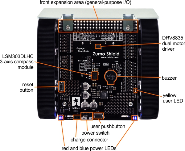
Les fonctionnalités de base du shield Zumo (v1.2) sont indiqués sur le diagramme suivant:

Pour le shield Zumo original, un diagramme correspond est disponible ici (206k, jpg) (la seule différence concerne le senseur intertiel placé sur la carte).
Alimentation
Le châssis Zumo dispose d'un comportement interne pour 4 piles AA. Pololu recommande l'utilisation de piles NiMH AA rechargeables, ce qui représente une tension nominale de 4.8 V (1.2 V par pile). Vous pouvez également utiliser des piles alcaline, ce qui produit une tension nominale de 6V.
La bordure arrière du shield Zumo reprend un connecteur femelle deux pôles connecté directement sur les connecteurs des piles. Ce connecteur peut être utilisé pour recharger les piles du Zumo sans retirer les piles du châssis. La broche positive du connecteur de recharge est sur la gauche et identifié par un signe (+). Un chargeur tel que le iMAX-B6AC lien pololu, connecté sur des fils de prototypage permet de recgarger directement le Zumo.
Après la protection contre la polarisation inverse accidentelle, la tension des piles est connecté sur le reste du shield par l'intermédiaire de l'interrupteur d'alimentation. Cette tension d'alimentation (derrière l'interrupteur) est désigné comme VBAT et fournit la puissance aux moteurs par l'intermédiaire du DRV8835. Un régulateur boost est également alimenté par VBAT et produit une tension de 7.45 V permettant d'alimenter votre Arduino par l'intermédiaire de la broche Vin. Par la suite, les régulateurs 5V et 3.3V de votre Arduino fournira la tension d'alimentation au contrôleur moteur (étage logique), au buzzer et à la boussole du Zumo Shield.
| Attention: lorsque vous alimentez votre Arduino depuis le shield Zumo, vous ne devez JAMAIS connecter une source d'alimentation différente sur la broche VIN -ou- connecteur d'alimentation de votre Arduino. Si vous le faites cela créera un court-circuit entre l'alimentation du shield et l'alimentation de l'Arduino, ce qui pourrait endommager votre Arduino et le shield Zumo de façon permanente. |
| Lorsque votre Arduino est connecté sur votre ordinateur par l'intermédiaire du port USB, votre Arduino sera alimenté (et produira du 5V et 3.3V sur le shield) même si l'interrupteur du shield Zumo est coupé. Cette fonctionnalité est bien pratique si vous voulez tester votre programme Arduino sans permettre aux moteurs de fonctionner (puisque l'interrupteur ouvert déconnecte l'alimentation VBAT des moteurs. |
LEDs
Il y a 5 LEDs sur le shield Zumo:
- Un enseble de LEDs d'alimentation (dite "Power" en anglais), l'une bleue et l'autre rouge, sont localisées sur chaque coin arrière du shield.
- Une LED utilisateur jaune est localisée sur le bord droit du shield. La LED est connectée sur la broche digitale 13 d'Arduino (en parallèle de celle présente sur la carte Arduino).
Boutons poussoirs
Deux boutons poussoirs peuvent être soudés sur le shield Zumo:
- Le bouton Reset est localisé sur le bord gauche du shield. Il est connecté sur la broche RESET d'Arduino et peut être pressé pour réinitialiser votre Arduino.
- Le bouton Utilisateur (dit "user" en anglasi) est localisé sur la bordure arrière du shield. Le bouton est connecté sur la broche digitale 12 de votre Arduino; Presser le bouton ramène le potentiel. Nous recommandons donc d'activer la résistance pull-up de la broche (pour maintenir la broche au niveau haut par défaut). La bibliothèque Pushbutton, inclus dans la bibliothèque du shield Zumo, permet de détecter plus facilement la pression du bouton (et applique un déparasitage logiciel).
Pilote moteur
An integrated DRV8835 dual motor driver on the Zumo Shield drives the Zumo’s two micro metal gearmotors. Four Arduino pins are used to control the driver:
- Digital pin 7 controls the right motor direction (LOW drives the motor forward, HIGH drives it in reverse).
- Digital pin 8 controls the left motor direction.
- Digital pin 9 controls the right motor speed with PWM (pulse width modulation).
- Digital pin 10 controls the left motor speed with PWM.
The ZumoMotors library provides functions that allow you to easily control the motors, and it can optionally take care of flipping a direction signal for you if you accidentally soldered in a motor backwards.
Buzzer
The Zumo Shield comes with a buzzer that can be used to generate simple sounds and music (for example, you could use it to produce an audible countdown at the beginning of a sumo match). The buzzer control line is labeled BZ on the shield; if you alternate between driving it high and low at a given frequency, the buzzer will produce sound at that frequency.
The ZumoBuzzer library uses hardware PWM to play notes on the buzzer, with digital pin 3 (OC2B) on an Arduino Uno or an older Arduino, or with digital pin 6 (OC4D) on an Arduino Leonardo or A-Star 32U4 Prime. A jumper is provided to connect the BZ input to the appropriate Arduino output, as detailed in Section 3.c.
Zone d'extension avant
A number of I/O, power, and ground connections are brought to the front of the Zumo Shield to allow the mounting of additional sensors and other components. The pinout of this front expansion area is detailed in Section 3.b.
Senseurs Inertiels
The Zumo Shield includes on-board inertial sensors, which can be used to sense acceleration and orientation for advanced applications:
- The v1.2 Zumo Shield features an LSM303D 3-axis accelerometer and magnetometer and an L3GD20H 3-axis gyroscope.
- The original Zumo Shield features an LSM303DLHC 3-axis accelerometer and magnetometer.
The inertial sensors are detailed in Section 3.d.
Basé sur "Zumo Shield for Arduino" de Pololu (www.pololu.com/docs/0J57) - Traduit en Français par shop.mchobby.be CC-BY-SA pour la traduction
Toute copie doit contenir ce crédit, lien vers cette page et la section "crédit de traduction". Traduit avec l'autorisation expresse de Pololu (www.pololu.com)
Based on "Zumo Shield for Arduino" from Pololu (www.pololu.com/docs/0J57) - Translated to French by shop.mchobby.be CC-BY-SA for the translation
Copies must includes this credit, link to this page and the section "crédit de traduction" (translation credit). Translated with the Pololu's authorization (www.pololu.com)